Spis treści
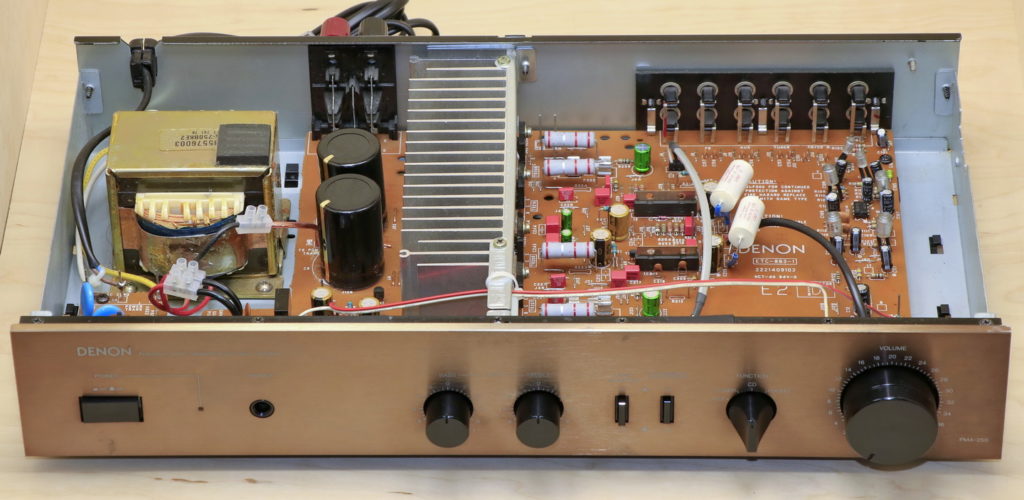
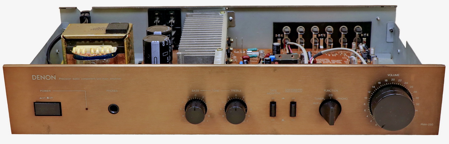
The Denon PMA-250 is an amplifier from the end of 80s, which despite the passage of time can still show class. Its sound is pleasant, musical, with a large dose of emotion. It gives a lot of listening pleasure, allows to relax and enjoy the music.
Of course, the PMA-250 has some disadvantages, but with its current price, it is a very good proposition for people who like to flow with a melody, and put sound control in the further place. When it comes to flaws, a lack of resolution and control of lower registers can be heard from the first moments. When more than one instrument appears at the bottom of the band, problems begins. The sound begins to merge and create uniform wall of bas. This behavior appears even with low power, which is quite strange considering the relatively large transformer and large power capacitors. The vocals are pleasantly exposed and they have a lot of space. In fact, only the middle range can show good separation. The upper range is correct, but it lacks a finish that would definitely improve the stage. It is clearly heard that the upper range is muffled and “lacks wings”. The amplifier cannot be accused of lack of energy and power. Even with louder playing, I didn’t get the impression that he lacked power (within reason, of course). It can be heard that the amplifier has the desire and ambition to play, which makes me perceive it very positively and see in it a lot of potential.
Cleaning and repairing damage
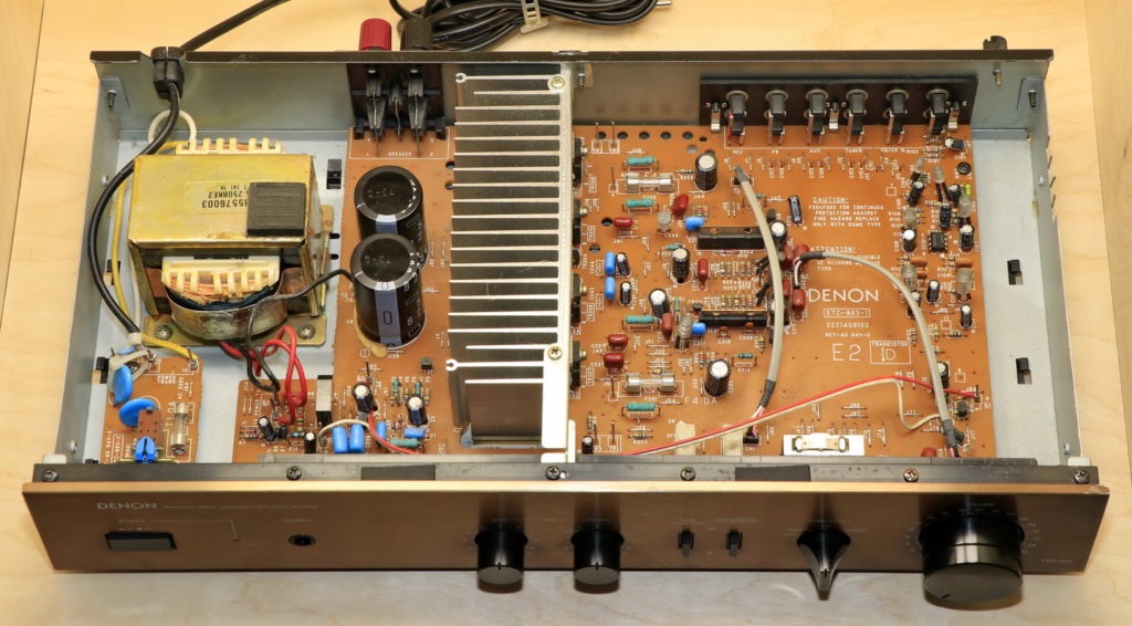
The specimen which I got in my hands has already been repaired. Although what has been done in this amplifier is hard to call repair. Fortunately, there was not much changes and the only points that needed improvement were a damaged volume potentiometer and ripped paths at the power switch.
Replacing the volume potentiometer
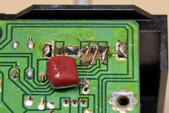
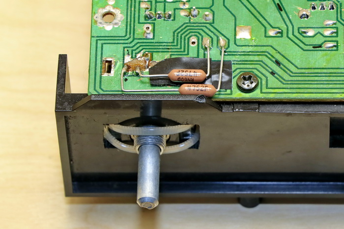
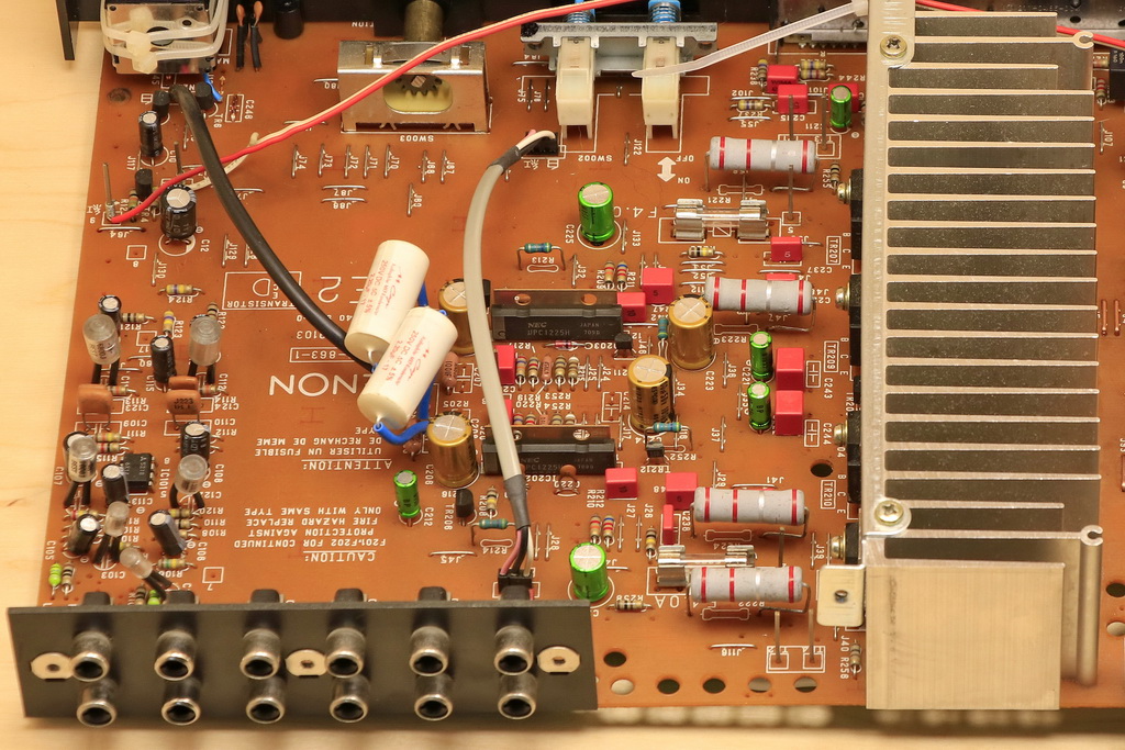
When I first saw what was done with the volume potentiometer, I was a little scared and worried that this could be the end of this amplifier. The potentiometer was glued, pins was solder to 1.5mm wire, additionally all paths on PCB was damaged and ripped.

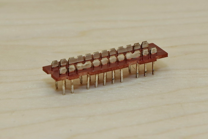
There were no descriptions on the potentiometer, but I am pretty sure it is an ALPS design, because it turned out that the currently produced model of potentiometer ALPS RK168 matches the pins on the printed circuit board. RK168 is a potentiometer with electric control, so its adjustment required some work. I removed the motor of the electric control because there was no room for it. The potentiometer is mounted quite high, so the factory pins did not reach into the PCB. I solved this problem by soldering 0.5mm copper wire to the pins. I put the potentiometer in the mounting socket and fix it with the help of cable tie. The factory potentiometer was 100k ohms, while the potentiometer I could buy at the time of modification was 50k ohms. The smaller value of the potentiometer was compensated by adding 47.5k ohm resistor in series with the potentiometer. I am aware that this limits the range of the regulation, but in practice, with normal use, such a solution is imperceptible.
Replacing the potentiometer with RK168 brought additional benefits in the form of smoother volume regulation. The damaged potentiometer had a linear characteristic, which caused a large increase in the value of the signal with small potentiometer variations. RK168 has logarithmic characteristics, which significantly improves comfort and control range in the useful volume range.
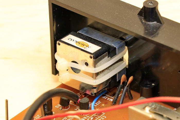
Cleaning the input selector and DIRECT CD switch
Cleaning of switches and potentiometers is the first and obligatory procedure that should be carried out before making any modifications. Over the years of use, oxidation occurs in all mechanical components, which has a significant impact on the sound of the device. Therefore, the selection of components for the device with dirty switches and potentiometers makes no sense.
Usually I don’t document the cleaning of mechanical components, but in this case I decided to make an exception for two reasons. The first reason was the deplorable condition of the input sector, which required a lot of work to be cleaned. The second reason was the DIRECT CD switch, which allows bypassing the input selector and the TAPE MONITOR switch, which ensures direct signal transfer to the amplifier module input. In principle, the DIRECT CD switch is very important, because the signal always flows through it, regardless of its position, so cleaning only the input selector does not remove all pollutions from the signal path.
Replacement of capacitors
Power capacitors
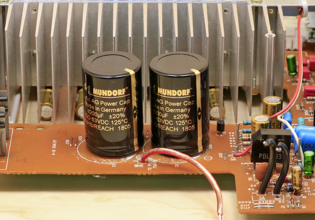
Denon PMA-250 is an aged construction, which certainly has an impact on the condition of electrolytic capacitors. I decided that the factory capacitors will be replaced by Mundorf M-Lytic capacitors. These are great capacitors with very low series resistance. I decided not to change the value of the capacitors and stay at 8200uF. Denon sounds quite warm and musically, he is not the king of dynamics and analyticity, and increasing the capacitor capacity could cause too much blur of the sound. The factory capacitors had 3 leads, however, matching the Mundorfs capacitors did not cause major problems and only required the use of jumpers.
The replacement of capacitors made that the lowest registers gained more breath and began to engage more. Thanks to the better efficiency of the new capacitors, the dynamics and bass speed also increased, which well compensated the lower range. The changes were very positive, but I knew from experience that this is not all that can be obtained from Mundorf capacitors. Capabilities of capacitor are one thing, however supplying energy from this capacitor to the power amplifier is another. I resolved this problem by thickening the PCB paths, which I describe in the section below regarding the amplifier’s PCB corrections.
Collector capacitors
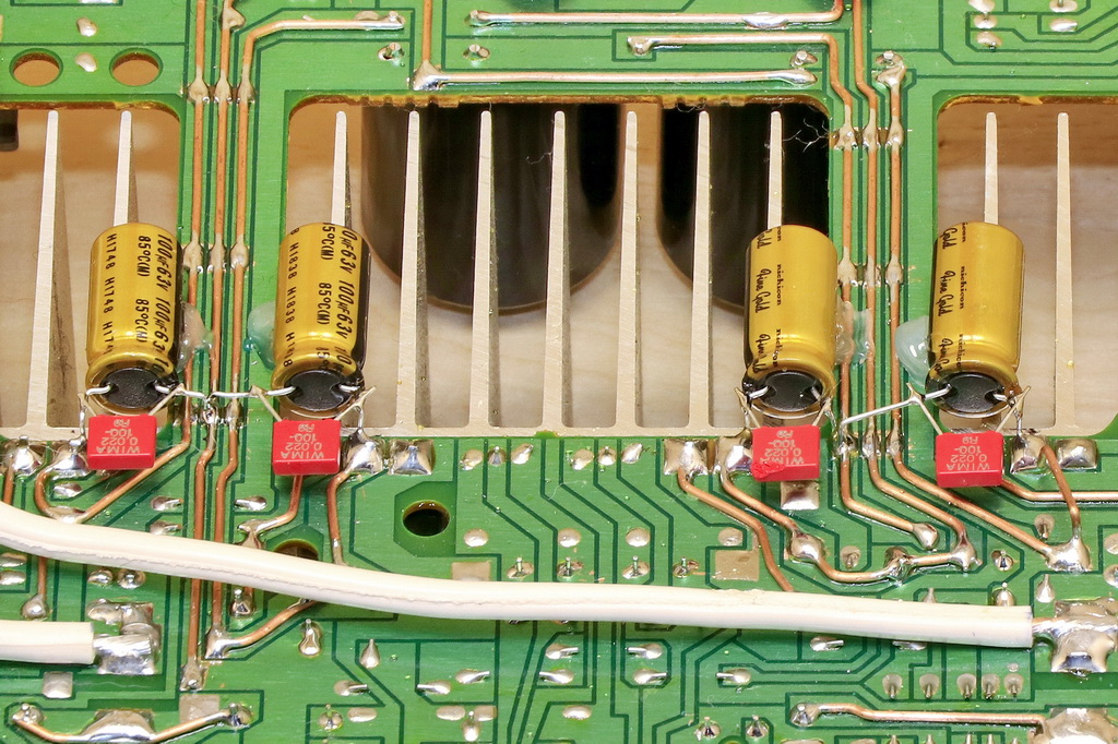
Another change to improve the amplifier’s current efficiency was the addition of collector capacitors. The distance between Mundorf M-Lytic capacitors and power transistors is quite large, in addition, the paths are not uniform, but crossed with jumpers, which negatively affects the cross-section of the paths even when they are thickened. I decided to compensate the losses resulting from the length and quality of the paths by adding to each collector of the power transistors electrolytic capacitor Nichicon Fine Gold, with a capacity of 100uF. It turned out that this change was very necessary. A 100uF capacity is not much, but thanks to it the sound gained more air and freedom. The midrange gained the most from this change, the vocals got more space and naturalness, the instruments became more tangible. The lower range also gained a better cut.
This example shows that even small (almost negligible) obstacles can have an audible and significant effect on the sound quality of the amplifier. Therefore, a lot depends on careful consideration of the design and consideration of even insignificant dependencies from electrical side.
Electrolytic and decoupling capacitors
The amplifier construction is based on NEC uPC1225H integrated circuits. Thanks to this it is not complicated and in the amplifier itself there are only 4 electrolytic power capacitors, two for each uPC1225H integrated circuit. The other two capacitors are located on the power input and are responsible for the power quality of the phono input operational amplifier. I decided that, as in the case of collector capacitors I will use Nichicon Fine Gold capacitors.
The issue of decoupling capacitors was a little more complicated due to the large distance between the power input and power transistors. I decided to use capacitors with smaller capacity at many points of the power path. As usual, WIMA MKS2 capacitors have proven themselves in this application. I installed the first pair of 0.022uF capacitors at the rectifier bridge, the next pair went to Mundorf M-Lytic power capacitors. Further capacitors were installed at each additional collector capacitor. The amplifier has factory decoupling capacitors next to power transistors, these are capacitors C227, C237, C228, C238, however their arrangement is not optimal and they are located quite a distance from the collectors of the transistors. I also replaced the factory capacitors with WIMA MKS2, because despite their not very good location, they always constitute an additional power decoupling point. The last place to add decoupling capacitors was the supply of uPC1225H integrated circuits. In this place I used 0.1uF capacitors.
I do not know how much I gained thanks to many decoupling points, because I did not do comparative tests for a smaller number of decoupling capacitors, but the final effect of the implemented solution is very good. Noise introduced by the power supply has decreased, more space and a black background have appeared.
Foil capacitors
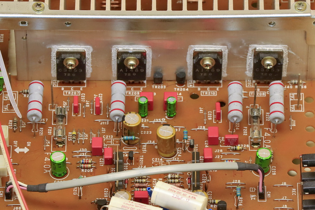
Denon PMA-250 has several foil capacitors, which are the filtering and tuning elements of the amplifier. These are the elements in the signal path and have a direct impact on the sound of the amplifier. I decided to replace the factory capacitors with one of the best capacitors for use in the audio path, which are WIMA FKP2 (red rectangles in the photo below). FKP2 capacitors introduced positive changes, the sound became more clear and arranged, and at the same time did not lose musicality. FKP2 are very good capacitors, however, using them requires caution, that the sound does not become too raw and without emotions. Denon reacted very well to these capacitors and lost nothing of his emotional message. The photo below contains 10% tolerance capacitors, these are C217 and C218 capacitors. There is quite a lot for audio applications, however, all capacitors with a tolerance of more than 5% are measured and paired by me to minimize differences in channel divergence. Unfortunately, sometimes components with better tolerance are not available and I have to use measuring instruments to maintain a decent convergence of parameters.
The picture below also contains two Mundorf M-Cap capacitors, these are capacitors between the volume potentiometer and the signal input of the uPC1225H integrated circuits. I decided to use Mundorf M-Cap because these capacitors match the character of this amplifier very well. In addition, they introduced positive changes, softened slightly higher registers and gave them more complete shapes.
Corrections of PCB
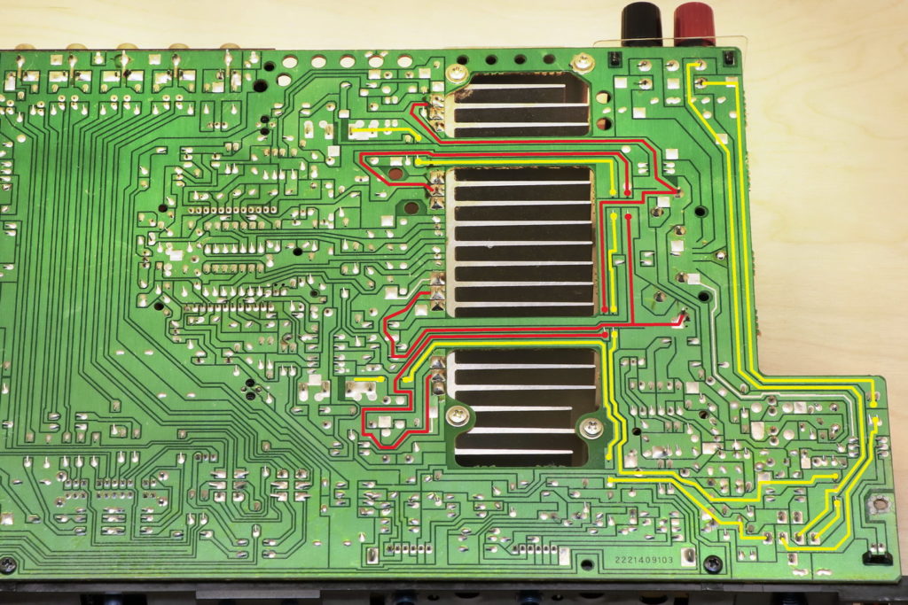
Denon PMA-250 is an example of an amplifier that shows how difficult task can be to design a printed circuit board. Looking from the side of the elements, everything seems fine, the power supply comes from the left, is rectified and fed to the power capacitors. The whole is well separated by a heat sink, which is a screen for the part of the amplifier responsible for processing the audio signal. Problems begins when one analyzes the way of lead the PCBs paths. The power supply paths have a small cross-section, which combined with the relatively large distance of the transistors from the power capacitors, creates problems with the amplifier’s current efficiency, which is clearly evident even at low power. Jumpers in the power supply paths are made of thin wire which also do not positively affect on power efficiency of the power supply.
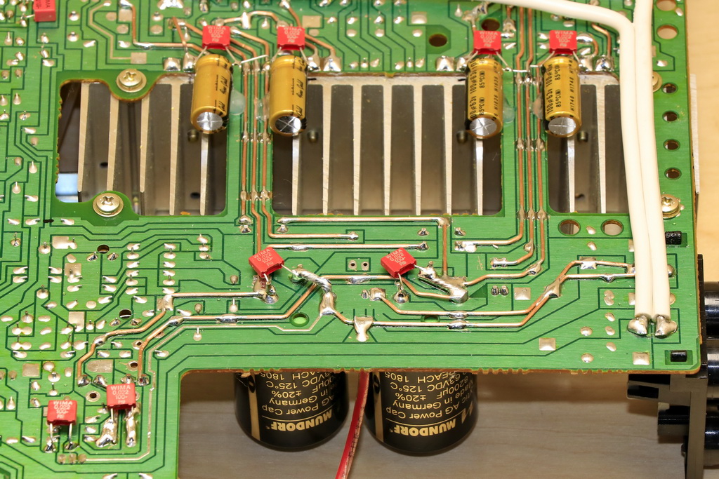
Even worse is the issue of leading signal paths between power transistors and amplifier output sockets. I can’t understand why Denon decided to lead the paths to the headphone jack first and then from that jack the paths go further to the output sockets. Of course, there are many thin wire jumpers along the way. Below is a photo showing the leading of the power paths (red lines) and the signal paths between power transistors and the output sockets of the amplifier (yellow lines).
Increasing diameter of power paths
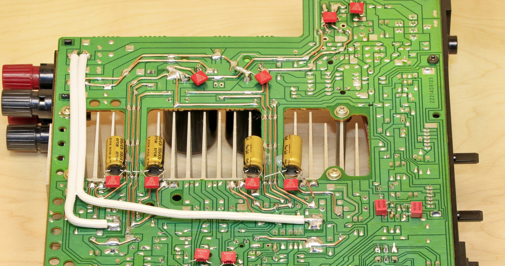
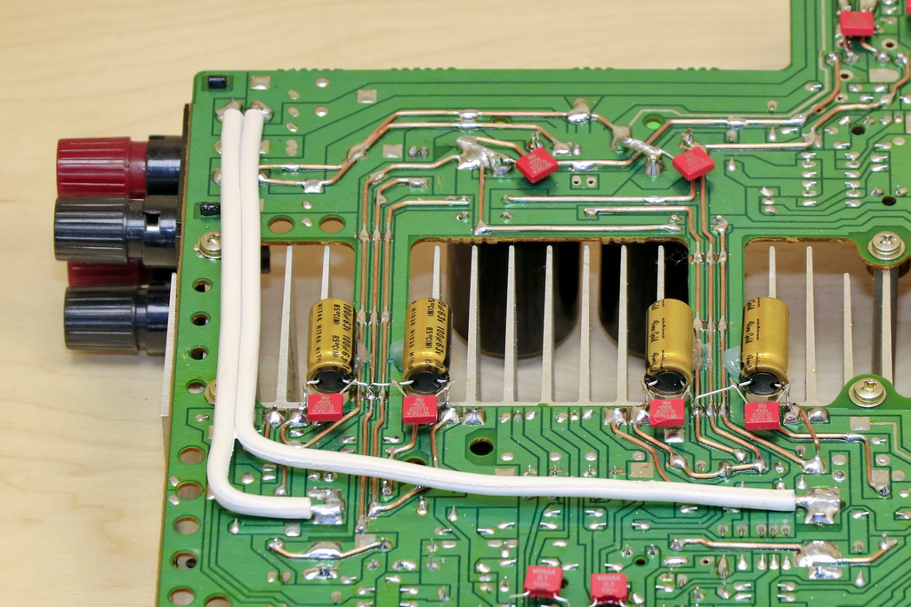
To improve the energy flow to power transistors and fully use the potential of Mundorf M-Lytic capacitors, I decided to improve the diameter of the power paths by adding copper wire with a diameter of 1mm^2 to them. All jumpers in the power paths have also been replaced with thicker ones. The photo below shows the final effect. The paths are thickened from the power input (rectifier bridge) to the power capacitors, and then from the power capacitors to the collectors of the power transistors. Making these connections required a lot of work, but listening sessions showed that it was a good idea. The amplifier began to cope better with higher loads and began to maintain decent dynamics with clearly more power. The changes that have taken place have also confirmed my earlier suspicion that the use of high-quality power capacitors for this amplifier does not bring the expected benefits if the power paths are not improved.
Signal output paths improvements
Leading signal output paths on the circuit board is solved in the worst possible way. I can’t understand why someone led the paths first to the headphone output and only then to the speaker connectors. This significantly expanded the signal path length. Denon PMA-250 printed circuit board has a decent copper thickness (I estimate it is 35um on the basis of my experience), however, the little width of the paths and the relatively large length make this path certainly an audible obstacle to the output signal. In addition, the paths are crossed in many places by jumpers. I found it pointless to correct such paths. A much better and simpler solution was to lead additional cables between the power amplifier and speaker connectors. The connection was made with a 2.5mm^2 QED Performance cable (white cable in the picture below). As you can see in the picture, the cable is much shorter than the factory paths, and in addition it is uniform line, not intersected with thin jumpers. The changes introduced by the additional cable were immediately noticeable. Why did the manufacturer decide on such a solution? After all, the paths could be led to the headphone jack, and the connection to the speakers could be made with a cable. I do not think that the manufacturer was not aware of such a serious shortcoming. Maybe it was a matter of automated production.
Replacement of emitter resistors
Replacement of emitter resistors is the last change I made in this amplifier. Mundorf MR5 resistors work very well in this role and they have very good value for money. They present a mild and spatial sound, although these properties are rather due to the fact that they do not sharpen the sound, as is the case with cheaper resistors.
The changes introduced by replacing the emitter resistors were obviously positive. In addition to the mentioned gentleness and space, the dynamics improved, the bass became more firm and natural. In principle, from my own experience, I can say that these resistors are rather transparent to the sound, they do not try to impose its character on it, but only carry what is already in this sound.
Summary
I’m happy with the results of my work with the Denon PMA-250 amplifier. Its biggest drawback turned out to be not best leading of the paths and it took me the longest time to solve this problem. However, the effect obtained is very good. The amplifier still plays musically and gives a lot of pleasure listening to music, so it still does what it does best, but now it does at a higher level. The message has more life, Denon copes better with more sources, plays with clearly greater involvement. The cost of the changes was not small and significantly exceeded the purchase price of the amplifier, but the final result showed that it was a good investment, because it is hard to find such a mature sound in modern designs. The Denon PMA-250 is not a power demon, but for listening the music at home it works great and does it at a relatively low cost.