modification

Nostromo Valentine

Nostromo Valentine

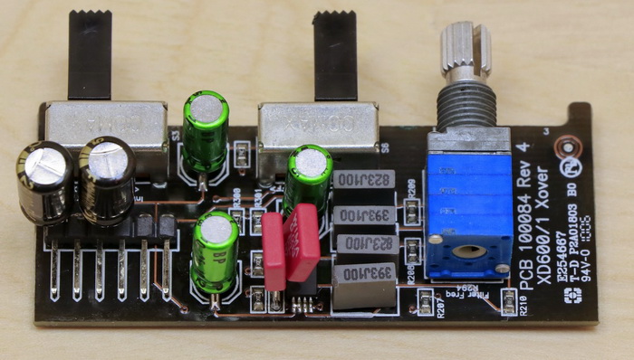
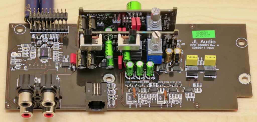
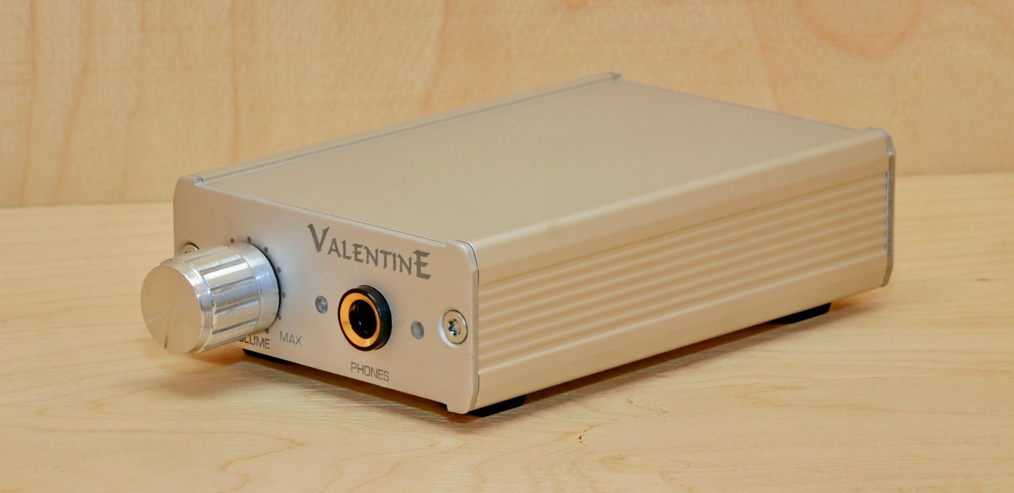
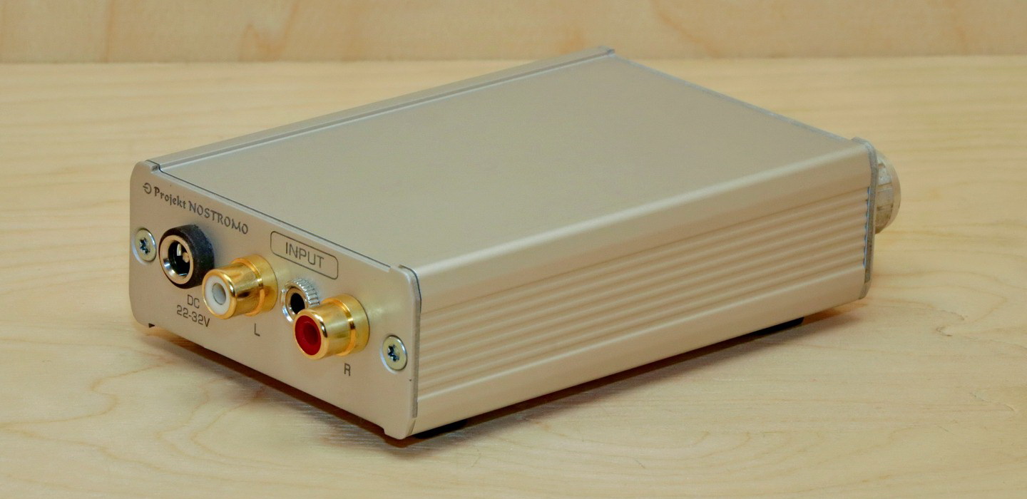
Nostromo Valentine is a small-sized headphone amplifier of Polish production. This is the first Projekt Nostromo company product I have dealt with. Products of Projekt Nostromo company have a good reputation and when one of my friends suggested that he would send me his headphone amplifier, to check if I can improve its sound, I was very enthusiastic, because people who had the opportunity to listen to Nostromo Valentine, express themselves about this headphone amplifier very positively.

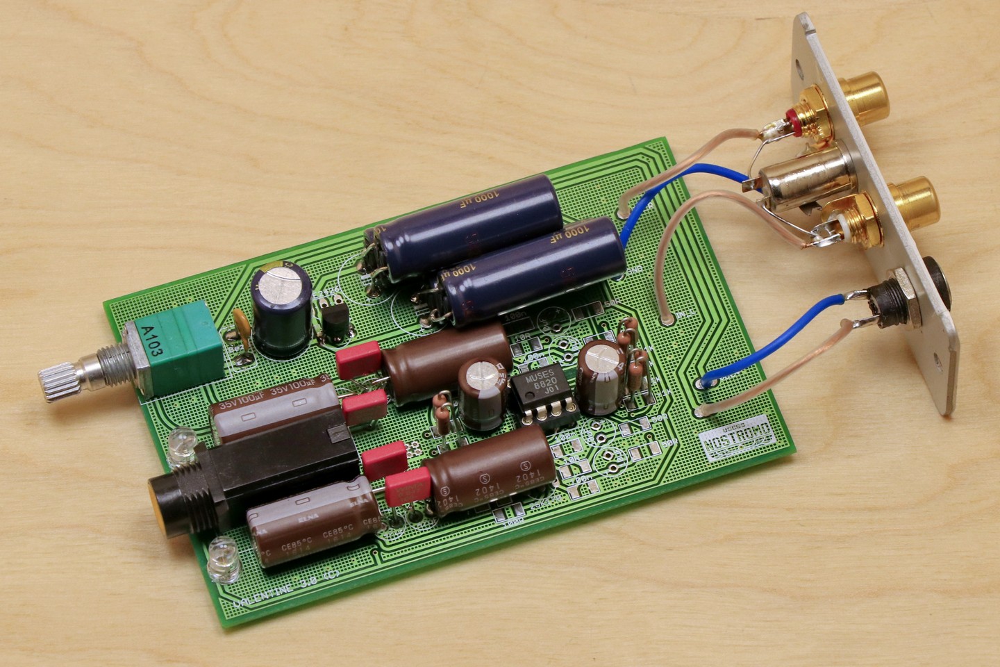
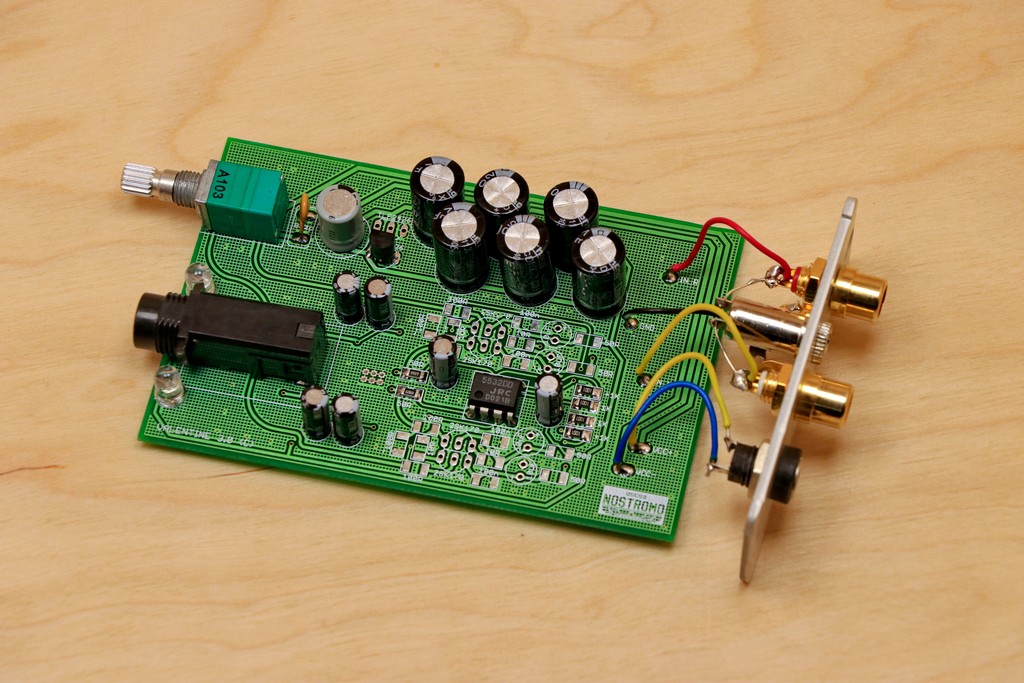
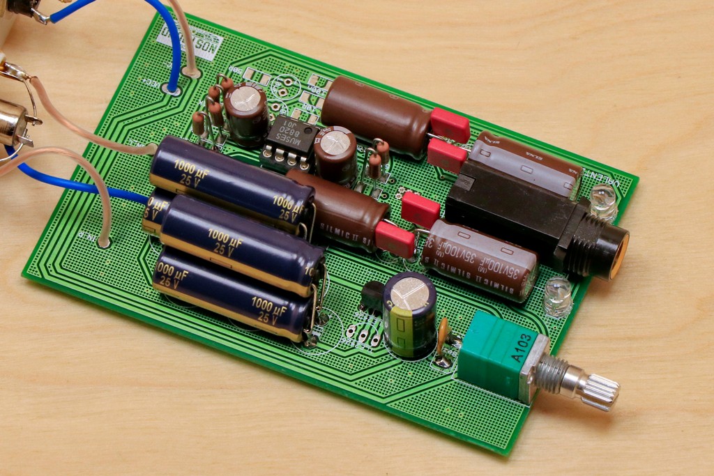
Nostromo Valentine is a cheap design and I did not expect much from this amplifier, but I was hoping that with such positive users feedback, the amplifier would offer something more than what its price would suggest. Before the first listening session, I decided to look inside the amplifier. The design of the Nostromo Valentine is very modest and, to put it simply, consists of a potentiometer, an operational amplifier and a headphone amplifier integrated circuit. The implementation of opamp and headphone amplifier integrated circuits is very simple and minimally interferes with the input signal. Personally, I like simple solutions, because any interference in the signal always degrades it to some extent, although well-chosen filters can bring a lot of positive changes to the sound.

After assembling the amplifier, it was time for the first listening sessions and, unfortunately, quite a disappointment. The sound that I heard was withdrawn, uniform, even stripped of dynamics. There was nothing in this sound that could be considered a positive feature. At first I thought something was wrong with connections or signal source, but everything was fine. I have dealt with the TPA6120 chip and the NE5532 operational amplifier more than once and I have never come across a design that would castrate the sound so significantly, so I knew that in Nostromo Valentine is still a lot of options for improvement.

Operational amplifier modifications

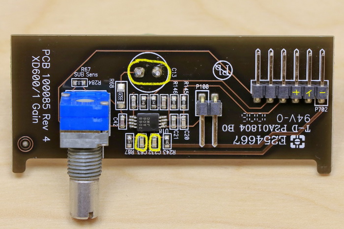
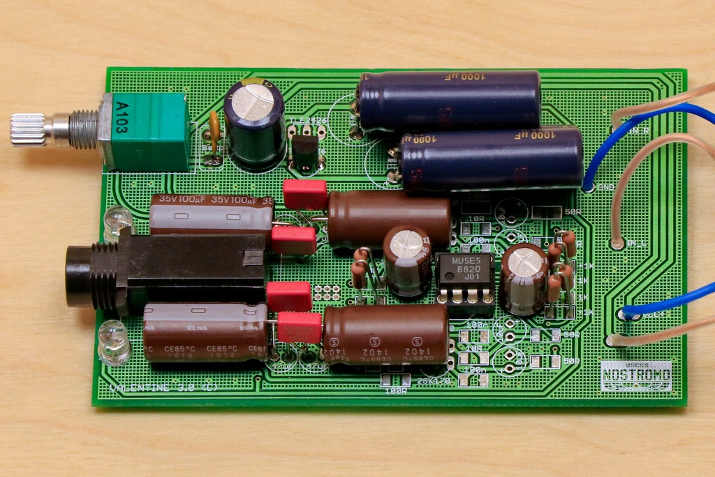
Nostromo Valentine uses a very simple implementation of an operational amplifier, based on the popular NE5532 integrated circuit. Opamp does not have any sound tuning function, it only prepares the signal for the TPA6120 integrated circuit. I decided to install a socket for an operational amplifier so that it was possible to replace the integrated circuits, and thus change the sound of the amplifier. The default configuration and tuning I was done for my favorite MUSES 8820 chip. The changes after replacing the opamp were very positive and the sound improved in every aspect. I must admit that I myself was surprised how big the changes took place after the replacement of the opamp. It is possible that this is due to a simple implementation that does not limit the opamp in any way, or factory fitted JRC NE5532 chip, was simply poor quality specimen.

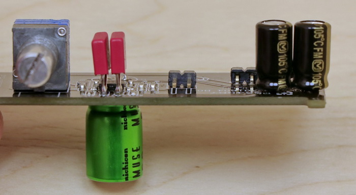
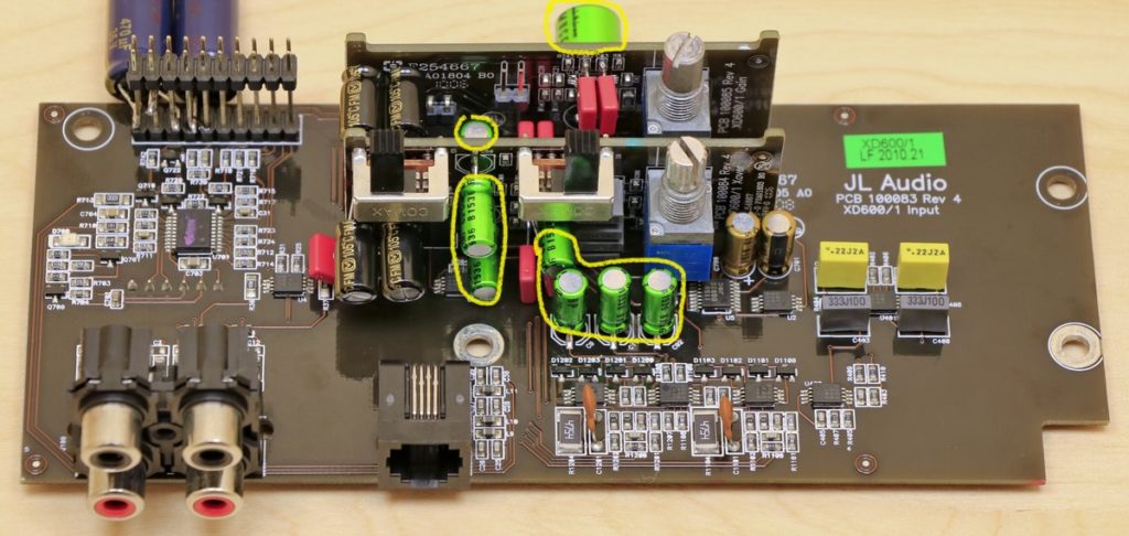
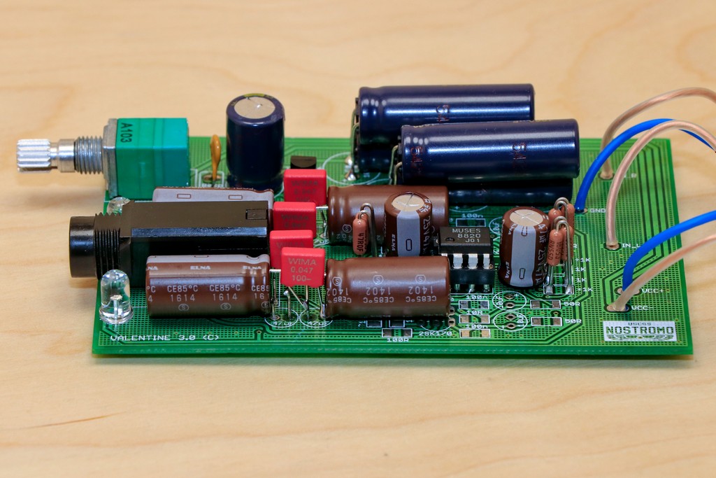
The next step was to picking electrolytic capacitors suitable for this implementation. In this case, the ELNA SILMIC II capacitors with a parameters of 47uF/35V proved to be the best solution. ELNA SILMIC II fits very well with the MUSES 8820 chip, providing a dynamic and clear presentation. MUSES 8820 has the opinion of an opamp that favors the lower and upper registers, but in combination with ELNA SILMIC II capacitors, is obtained a well-balanced and engaging sound.

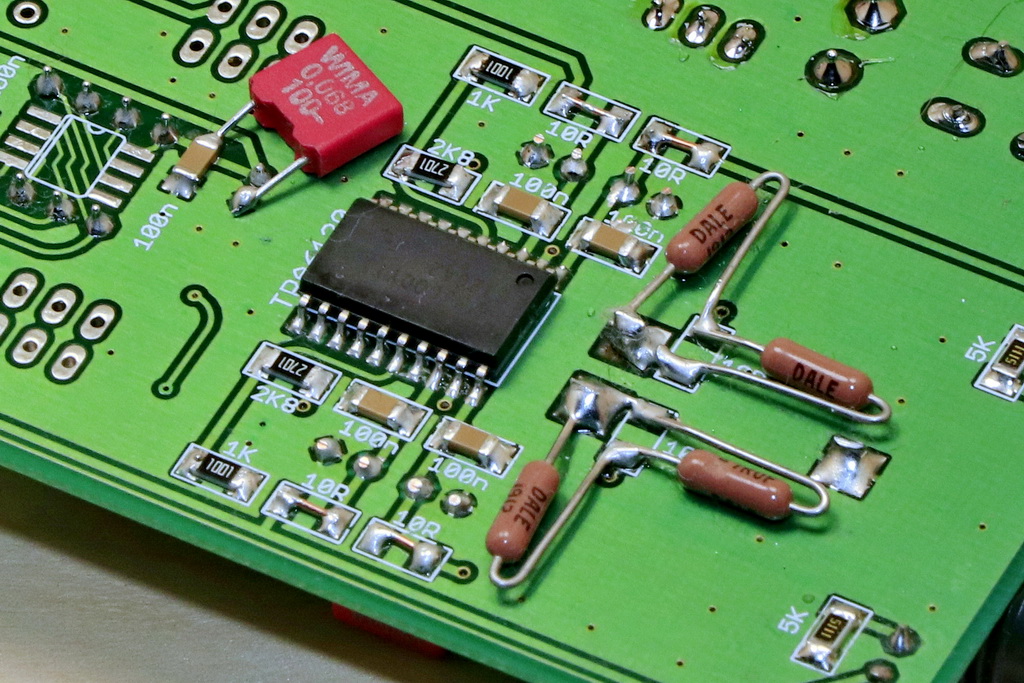
The next stage of the modification was the replacement of SMD resistors with Vishay DALE resistors. I used the RN55 version resistors because the larger RN60 did not fit between the housing and the bottom side of the PCB. The Vishay DALE resistors showed class as usual, adding better filling and an analog note to the sound. I have yet to come across an implementation where Vishay DALE would introduce any unwanted effects. There have been times when they have been able to soften the sound too much, but correcting this change is not a big problem. The action of Vishay DALE can be compared to a change in the weather, when we realize that the wind that we have been hearing all the time has finally died down and all the sounds that we were aware of begin, starts to reach us better thanks to the silence that has been created, but now they are fuller, more detailed, better placed in space.

The last stage of work on the opamp section was the selection of the appropriate decoupling capacitors. The operational amplifier was equipped with 100nF SMD decoupling capacitors, but I decided to add foil capacitors for this set. As usual, I used my favorite WIMA MKS2 capacitors and in this implementation the 68nF capacitance proved the best, it provided better separation and transparency, and at the same time did not take away too much musicality from the sound.

TPA6120 headphone amplifier circuits modifications

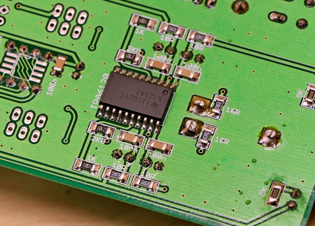
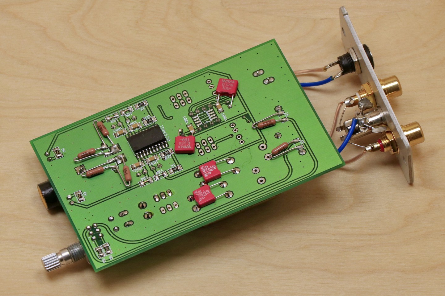
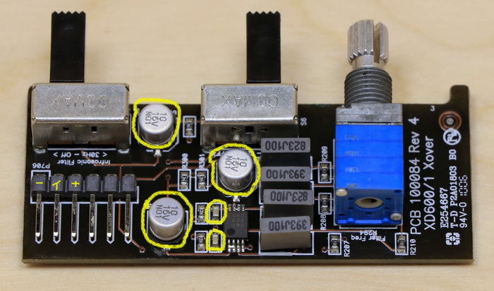
The first changes that I decided to make for the TPA6120 chip were changes to the power supply. The power supply of the amplifier circuit chip consists of a 10 ohm resistor, a 33uF electrolytic capacitor and a 100nF decoupling capacitor.

The combination of a 10 ohm resistor and a 33uF capacitor is one of the TPA6120 tuning points. This solution is to calm down and soften the character of the amplifier, but I didn’t like it very much. I believe that power-generating elements, no matter what the values, whether they are milli watts or watts, should not have a limited power supply, because this causes sound deformation, and the level of these deformations depends on the load value.

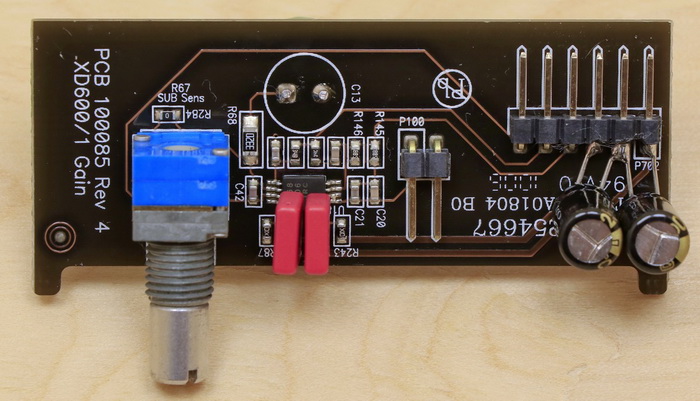
Therefore, I decided to remove the resistors from the power supply and replace them with a jumper. I also decided to increase the capacity of the electrolytic capacitors to 220uF, which is the highest possible value that could be contained in the housing. The effect was very positive, the amplifier started to sound completely different, the sound gained a lot of life and energy. Unfortunately, there were also negative effects in the form of considerable pushiness and lack of order. I expected such an effect and to correct the defects, I changed the value of the output resistors located between the TPA6120 chip and the headphone output from 10 ohms to 22 ohms.

Before I finally chose the value of the output resistors, I tested various values in the range of 10-47 ohms and the value of 22 ohms turned out to be the best solution, still providing great openness and dynamics, and at the same time eliminating the drawbacks resulting from removing the resistors from the power supply. Used resistors are of course the Vishay DALE in RN55 version. The photos show 4 resistors mounted on PCB. This is due to the fact that I didn’t have 22 ohms resistors in my collection in RN55 version, so I used two 47 ohm resistors connected in parallel, which gave a value of 23.5 ohms.

The next stage of the modification was the selection of the appropriate value of the electrolytic capacitors of the TPA6120 power supply. The capacitance of 220uF caused tonal balance disturbance and too high level of lower registers. The bass was not deformed or dominant and I suspect that many people would like it, but I tried to achieve the best possible balance of the sound. Before I choosed appropriate capacitors, I tested ELNA SILMIC II and Nichicon FineGold capacitors with capacities in 47-220uF range. Nichicon FineGold capacitors offered a calmer, more balanced sound. However, in the end, I chose ELNA SILMIC II capacitors with 100uF capacitance, which provide more energy, openness and a sense of communing with music compared to Nichicon FineGold capacitors. I recommend testing different variants of capacitors, because a lot depends on the design of the headphones and the preferences of the listener, but even with open headphones, the 100uF capacity ensures a sufficient number of lower registers. For closed headphones, even 47uF capacity can be enough.

The last stage of changes was the selection of appropriate decoupling capacitors. In this case, WIMA MKS2 capacitors with a capacity of 47nF proved to be the best. The 47nF capacitance added more air and widened the stage, but at the same time did not take away the plasticity of the sound, which is sometimes the case when the decoupling capacitors have too high capacitance.

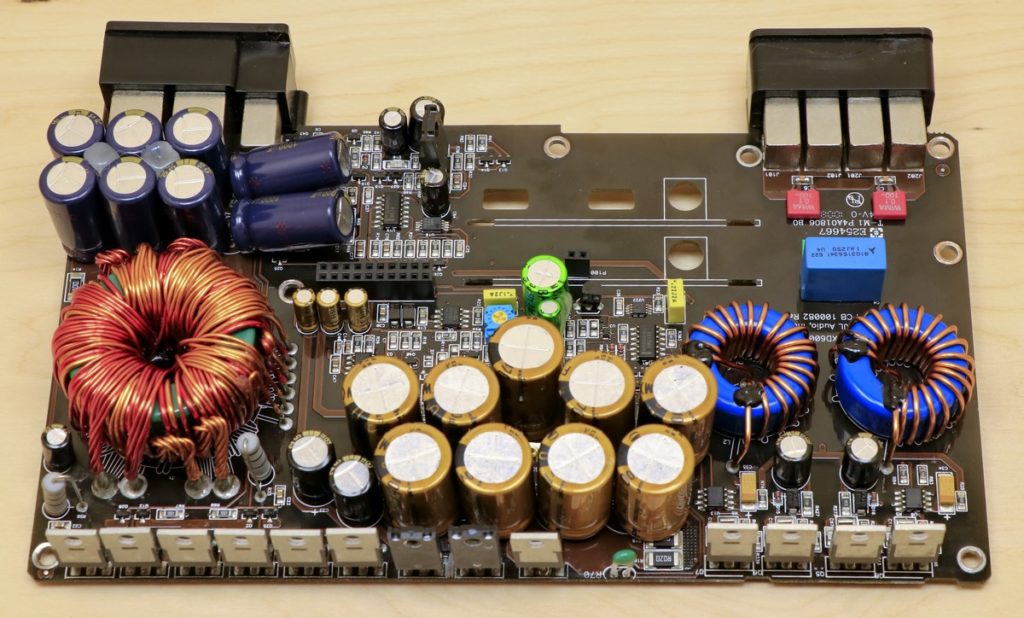
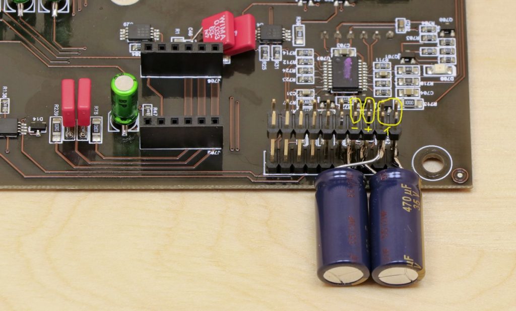
Amplifier power supply modifications

This will be a very short description, because Nostromo Valentine has been designed so that the input of the amplifier is supplied with already prepared, good quality power supply. In the housing of the amplifier itself there is only a battery of electrolytic capacitors 6x 1000uF/25V. I had a dilemma with these capacitors, because used capacitors were small and nothing bigger could fit into the housing. All the high-quality capacitors I use have much larger dimensions than the Chong capacitors used. It turned out that the only possible solution is to use Panasonic FC capacitors, which have dimensions that allow to fit four 1000uF/25V capacitors in the housing in the lying position. I used the remaining mounting places to mount additional WIMA MKS2 decoupling capacitors with a capacity of 33nF. I believe that the filtering properties of the capacitors are more important in this case than the summary capacitance itself, and the known character of the Panasonic FC, which provided a good basis for other changes. There is one more capacitor next to the potentiometer with parameters 47uF/63V. I replaced this capacitor with a Panasonic FC 330uF/35V. The permissible voltage of this capacitor is a bit too low for the maximum permissible supply voltage of the amplifier, which is 32V. However, in the case of a 24V power supply, it is a sufficient value, and this is the voltage of the power supply unit, which I have received with the amplifier, so I decided to use a capacitor with a higher capacity and a voltage of 35V.

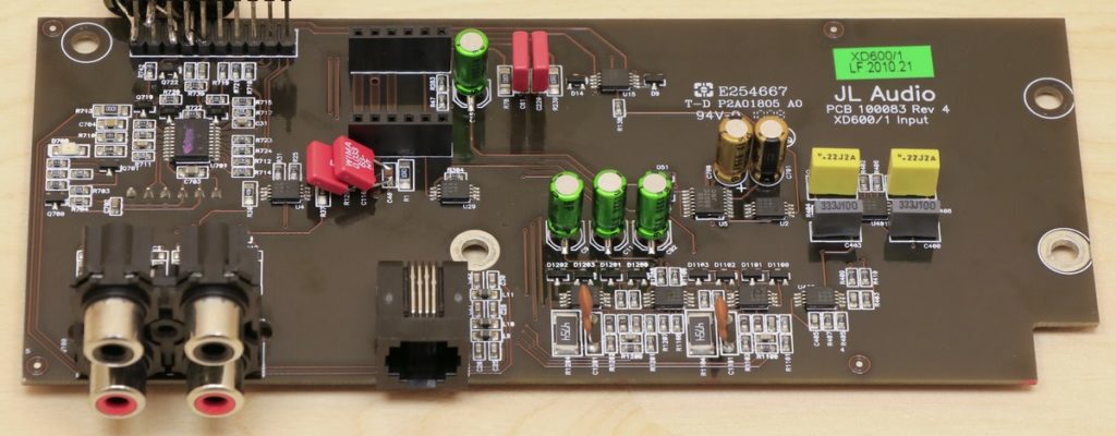
Nostromo power supply unit

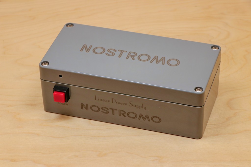
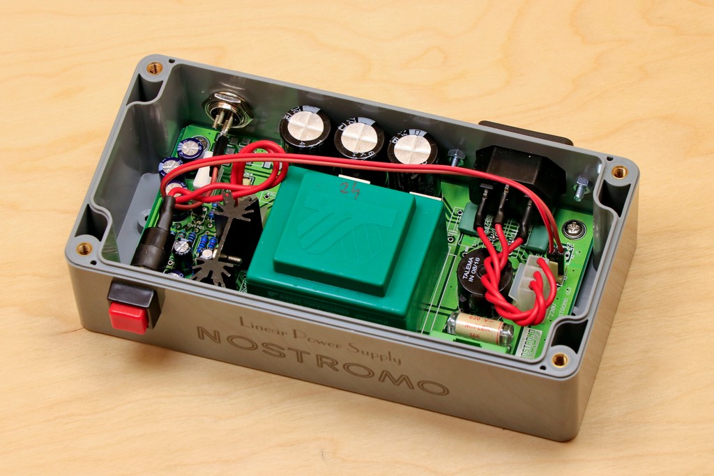
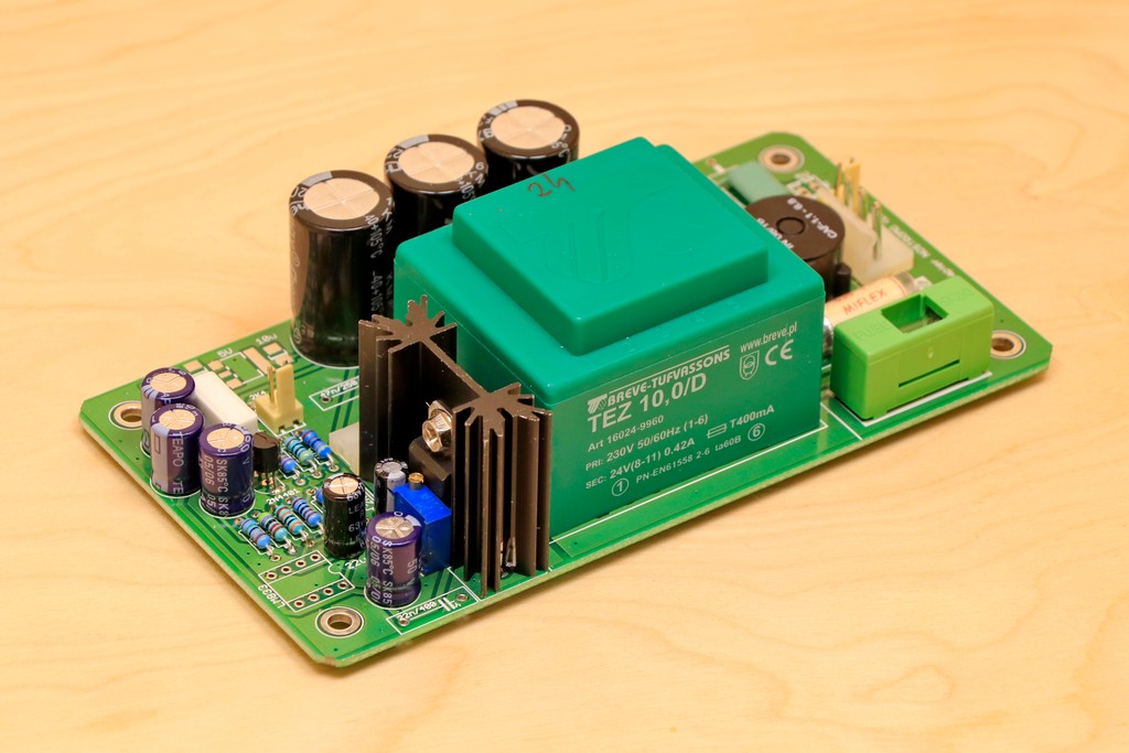
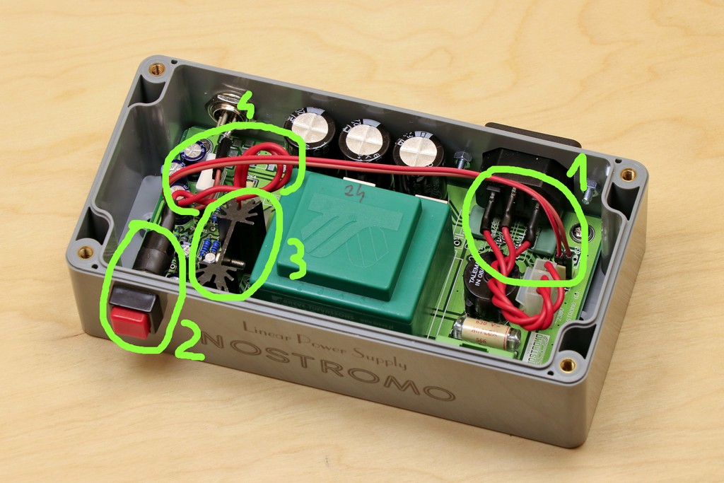
The Nostromo Valentine amplifier has such small dimensions due to the fact that the whole task of providing good quality power rests on the external power supply. Together with the amplifier I received a dedicated Nostromo linear power supply. I also planned to change this power supply to improve the quality of the power supply, but I gave up on this plan. The reason was too many design flaws that made any changes pointless. The elements used themselves are not the worst quality, but their arrangement is completely incomprehensible. The mains supply section is not separated at all and the mains circuits are intertwined with the output voltage circuits in many places of the construction.

Below are described my observations regarding the design of the power supply.

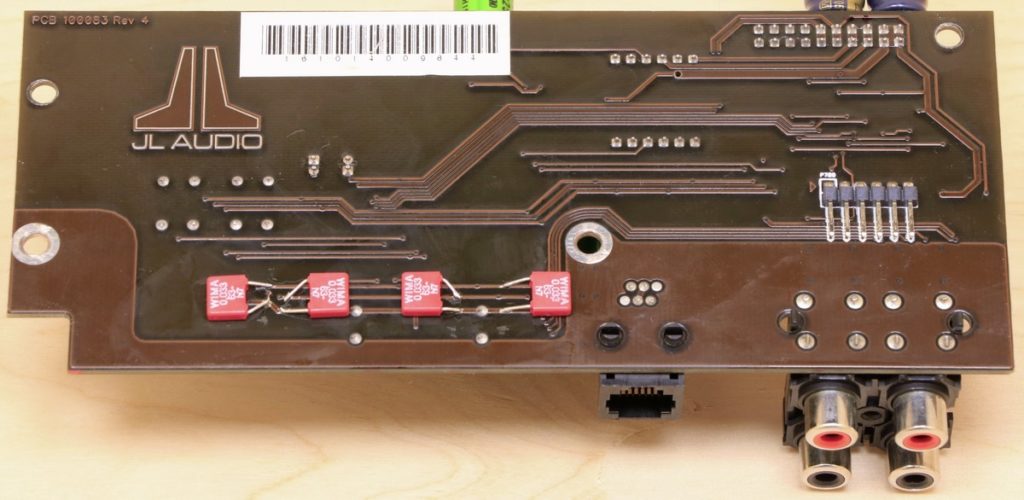
  1. The place on the PCB where mains power supply socket is located and at the same time the point from which the output voltage comes out from PCB. The wire that carries the output voltage to the output socket is located very close to the mains power supply socket wires. I do not understand why the output voltage is transferred to the other side of the PCB and then returned to the output socket with a wire.

  2. The power switch to which the mains power is applied is located on the other side of the housing, in relation to the mains socket, so that the mains voltage unnecessarily passes through half of the PCB. Why was the mains power switch placed in such a place? It could be placed close to mains power input, there is enough space above the fuse.

  3. The power regulator chip is screwed to the heat sink, without an insulating pad. This makes the heat sink act as an antenna and collects noise from the wires from the mains power switch located nearby.

  4. Another point where the cable connected to the output socket is close to the mains cables, this time from the power switch.

This design makes the mains noise propagate throughout the power supply. Which limits the effectiveness of the applied mains filter. In order to confirm my observations, I decided to check what changes will occur when the amplifier is powered from a 24V battery. My assumptions were confirmed because the changes were well audible. Better space, control, treble quality, better consistency and precision, overall more mature sound. Of course, there are no power supplies that can completely eliminate mains interference. But from my experience creating power supplies, I know that you can make a power supply that is not much different from a battery. In the case of the Nostromo Valentine amplifier power supply, it would be enough to make a few design changes to separate the mains circuit from the rest of the power supply.

Summary

Summarizing the end result, I usually try to describe the changes introduced by my work in relation to what the device presented before the modifications. However, in this case the changes were so huge that it’s hard to relate to what was before changes. In the amplifier, literally everything has changed. Nostromo Valentine now plays like 3-4 times more expensive constructions. The current sound is very dynamic, varied and colorful. There is a lot of air in it and a noticeable atmosphere and dimensions of the stage. The bass is varied with well-marked contours, it has quite a warm sound, but well-balanced and it can handle even fast songs without any problems, the middle range is very transparent with a lot of air and no sibilants. The upper range does not lag behind, the treble does not irritate and is nicely finished.

The sound obtained can be even improved if you replace the power supply with a better one. A better power supply makes the sound even more mature, especially in the upper and lower registers, where precision and control are improved.

Below I present the impressions of the amplifier owner after the first listening sessions, because this is probably the best possible summary.

This is it! Today I was very anxious because I was afraid of what I will hear …

At first I turned on Adele’s “Hello”, a few seconds and my jaw dropped, then a smile appeared from ear to ear. The bass is so incredibly springy now, there is a bit more of it, but it’s the WORLD CHAMPIONSHIP! Plus, it has many levels! How is this possible…? Moments later I turned on “Judith” A Perfect Circle and got goosebumps when Maynard started to howl. Now I turned on a mechanically playing Fear Factory band and the track “Replica”, which on the old construction was dry and cold, suddenly became PERFECT, with finally surprising bass present, I can hear the bass working, the chirping of drum cymbals and this air !!! The dynamics has jumped a few levels higher because I can hear everything in this confusion! Another dry album “Transgression” and “Mechanize” and I can’t believe what I hear … There is no colorless playing here anymore and I can catch individual tastes from the wall of sounds! The midrange seems to have slightly moved backwards, or it is simply warmer, because what I hear is no longer tiring! And now what I feared the most, i.e. the treble. They do not spark, there is no sibilants, slightly rounded, but this does not prevent the appearance of greater holography and space compared to what was before. I’m shocked how musical it is! The tracks I know are surprising every few seconds because there are sounds which was running away or I simply didn’t hear them before. What you did with this “box” is a masterpiece … I did not expect such a sound in the most daring imaginations. From one of the cheapest amplifiers (praised here and there) you have made a sensational-sounding device. The amount of air, compared to what it used to be, is much greater. Thanks to this dynamic, you can fall into a trance … What you wrote about him, that “there is more of everything”, is the shortest possible description. The stereophony and the depth of the stage have improved, the sound is more resolving. I quickly jumps through different genres of music and literally nothing sounds dry or bad anymore.

Posted by audiopurist in Modifications
Denon PMA-250

Denon PMA-250

The Denon PMA-250 is an amplifier from the end of 80s, which despite the passage of time can still show class. Its sound is pleasant, musical, with a large dose of emotion. It gives a lot of listening pleasure, allows to relax and enjoy the music. Continue reading →

Posted by audiopurist in Modifications
JL Audio XD600/1

JL Audio XD600/1

JL Audio XD 600/1 is a mono class D amplifier designed to power a car subwoofer. The amplifier has a power of 600W RMS at a load of 2 ohms. The presented specimen plays in the SQ (Sound Quality) system, and all introduced modifications were made with the aim of obtaining the highest possible sound quality. The work on this amplifier has greatly expanded my knowledge in the field of processing the lowest frequencies and confirmed how much the subwoofer influences the reception of the entire acoustic band, despite working in a very narrow frequency range (the low-pass filter of the amplifier is set to 65Hz/24dB/oct). The physical conditions in the car cause that the subwoofer, by its location (usually in the trunk) will always introduce some distortions, but I did not expected that so much of this interferences was emitted by the amplifier itself, which is not the cheapest construction. I consider the JL Audio XD 600/1 to be a good amplifier, worth it’s price, but the changes I’ve introduced have shown that much more can be obtained from this construction. Changes also showed that despite the placement of the subwoofer in the trunk, even small changes in the amplifier can significantly improve the reception of the entire audio system.

The factory XD600/1 presents the sound typical of the JL Audio constructions, the bass is compact, fast and precise. However, he lacks diversity, musicality and naturalness. I have always suspected that for those disadvantages were responsible loudspeakers that cooperated with the amplifier (Rainbown Vanadium 10 ‘, Hertz HX 300D), but it turned out that the problem was in the amplifier, which after the introduced changes significantly changed its face and now presents a completely different class of sound.

Subwoofer is irreplaceable element in car audio system, controversial in home audio system. There are people who can not live without it and those who can not stand the presence of a single bass speaker in the home audio system. I belong to the group of people who think that a single bass speaker in the home audio system introduces too much chaos on the stage and I hear it even when the subwoofer works with frequencies not exceeding 100Hz. People who decide to use a subwoofer should know that it is an integral part of the system, and it can not be simply turned on and off because turning off the subwoofer affects the other ranges of the audio band. Changes can be heard even in the reception of the highest registers, which become sharper and more present. Understanding the relationship and interconnection of all ranges of the acoustic band gives an idea of how much can be changed in the whole system, through changes even for a small acoustic range.

Construction of the amplifier

At the beginning I will briefly describe the construction of the amplifier so that the terminology I use is better understood. I do not intend to write about each block and its structure, I only describe what each of the amplifier’s PCBs is responsible for. The amplifier consists of 4 separate PCBs. The whole structure can be divided into two basic modules.

Amplifier module, containing power elements (converter, stabilizers) and the class D amplifier itself.

Amplifier module

Signal module, which is responsible for processing the audio signal, which then goes to the amplifier module. The signal module is responsible for receiving the signal from the sound source, adding up the signal (conversion stereo signal into mono), passing the signal through the low-pass filter (LPF) and adjusting the signal level (GAIN).

Signal module

GAIN adjustment and LPF filter were placed on separate PCBs. In addition, the signal module contains elements responsible for the PreOut output operation and the control of an additional external potentiometer for volume control.

This solution allows to preserve the compact design of the device, but combining the PCBs by copper pins can have a negative effect on the power supply quality of the active components and the transmission of the audio signal. Fortunately, the producer was aware of this disadvantage and the vast majority of paths are connected via at least 2 pins. The compact design also means that interference from the converter (which is not shielded) can be applied to an audio signal.

Replacing power capacitors

The amplifier has two batteries of power capacitors. The first capacitors battery is at the amplifier’s power supply input and consists of 8 capacitors with a capacity of 820uF. The second capacitors battery is located behind the converter and is a current reserve for the power amplifier, consisting of 9 capacitors with a capacity of 220uF.

The use of a large number of capacitors is a good solution for this construction. The battery of parallel connected capacitors has a much lower series resistance, which at high power, has a significant impact on the efficiency and effective operation of such a buffer.

When selecting the capacitors that were to replace the factory capacitors from SAMXON, the basic criterion was to keep the same number of capacitors and then to obtain the largest possible capacity. On the amplifier’s power input hit the PANASONIC FC capacitors with a capacity of 1000uF and voltage of 35V. The second battery behind the converter has been replaced by NICHICON FW capacitors. I have not used the NICHICON FW capacitors before and I decided to use them mainly because of their size, which allowed to use capacitors with a capacity of 470uF, instead of factory 220uF. At the beginning I was a bit skeptical about the Nichicon FW capacitors, so I decided to use the RLC laboratory meter to measure them. Thanks to this, I was able to check if the capacitors I chose have better parameters than factory capacitors.

The table below shows the results of measurements of series resistance of SAMXON factory capacitors, NICHICON FW and PANASONIC FC.


Series resistance

Series battery resistance

Battery capacity

SAMXON 220uF 100V

0,076 ohm

0,0084 ohm

1980uF

Nichicon FW 470uF 100V

0,052 ohm

0,0057 ohm

4230uF

SAMXON 820uF 35V

0,036 ohm

0,0045 ohm

6560uF

Panasonic FM 1000uF 35V

0,022 ohm

0,0028 ohm

8000uF

As can be seen in the table above, the replacement of capacitors has been beneficial in terms of both series resistance and capacitance. Particularly the replacement of capacitors to Nichicon FW resulted in more than double the capacity increase.

The measurements were made for frequencies from 1kHz to 10kHz, therefore they may differ from the catalog data. However, the main purpose of the measurements was to check the differences between the capacitors, and not verify the catalog data.

Differences in the values in the table are not only measurable, but also audible, especially at powers exceeding value 200W. The amplifier with factory capacitors was doing well, even with a nominal power of 600W. However, the exchange of capacitors showed that especially in the area of higher powers there were big changes in the dynamics. The amplifier is doing much better now and playing with more freedom.

The dimensions of the Nichicon FW and Panasonic FC capacitors are larger than the dimensions of factory capacitors, but the method of their assembly does not conflict and does not affect the other elements. The other electrolytic capacitors on the amplifier board are Panasonic FM, which I used because of their warm sound character. Also on the PCB are Nichicon FG capacitors which work well with Panasonic FM capacitors.

Addition of decoupling capacitors

Adding decoupling capacitors is one of the basic treatments during my modifications. In today’s audio devices a lot of attention is attached to this issue, but the common solution in the form of SMD surface elements makes that you can still gain a lot in this field. SMD capacitors have significantly worse interference filtering capacities than leaded foil capacitors, but their great advantage is the price and the ability to automate production, and thus reduce costs. Another advantage of SMD capacitors is their small size. This allows to bring the mass as close as possible to the power path, and such physical conditions in turn improve the efficiency of filtration. All this makes that sometimes it is not worth replacing the SMD capacitor with a foil capacitor. The best effects are obtained by combining both solutions, SMD and foil capacitor.

Amplifier module

There are many power decoupling points in the XD600/1 amplifier, which deserves praise. In some of the decoupling points there are no capacitors and empty places were left. Maybe it was considered that in the production version the assembly of capacitors at these points does not affect the improvement of quality. Sometimes too many decoupling capacitors can calm down the sound too much, so more does not always mean better. Of course, I decided to use available places and see how amplifier will reacts to this change.

As a decoupling capacitors I used WIMA MKS2 capacitors. In the case of this modification, I used 33nF capacitors. I usually use capacitors with a capacity of 100nF, but I decided that the capacity of 33uF will be safer in this case and will not negative affect the dynamics of the signal.

In the picture below can be seen the bottom part of the amplifier PCB, with added WIMA MKS2 decoupling capacitors. The most important places for this PCB is located in the lower left corner, where the decoupling capacitor was omitted at the very entrance of power supply of the amplifier, and in the upper right corner, where there are capacitors decoupling the power transistors. For the power output stage transistors is provided space for 4 SMD capacitors. The selection of decoupling capacitors for power transistors can be understood, but I don’t understand the lack of a decoupling capacitor at the power supply entrance and I consider it to be an excessive saving.

Signal module

The module contains 10 NJM2068 operational amplifiers. Part of the opamps are not provided with decoupling capacitors. These are opamps located next to external volume control socket, responsible for the PreOut output operation and for adding up the input signal (creating a mono signal for the power amplifier). I was able to add decoupling capacitors for these operational amplifiers by adding four capacitors to the power paths from the bottom of the PCB. In places where decoupling capacitors have been provided, WIMA MKS2 have been added to the SMD capacitors. In the pictures below, there are also Panasonic FM capacitors added for GAIN control and LPF filter power supply paths as well as Nichicon MUSE ES capacitors. Detailed information about them can be found in the next points of the modification.

Summary of addition of decoupling capacitors

I was very curious about what change I will get after adding decoupling capacitors in this amplifier. For amplifiers working in the full acoustic range, the effect is usually positive, but the biggest changes occur in the medium and upper band range, while in the lowest frequency range, they could even be unnoticeable. My fears dissipated after a moment of listening. I was amazed at how much the range of lower frequencies was cleansed. I have always suspected that the physical conditions prevailing in my car are main reason of the problems with the quality of the lower frequency range, but it turned out that the problem was also in the amplifier. The lower frequencies has gained more space and the so-called “black background”. XD600/1 is a construction that generates a lot of interference, the main source of which is the converter and EMI distortions characteristic of a class D amplifiers. All these distortions are frequencies of tens of kHz, but they must have a significant impact on the amplifier’s audio signal processing, even for such a narrow range of work, since the changes are clearly audible.

Addition of electrolytic capacitors in the audio signal processing module

In SQ (sound quality) systems, tens of watts of power can be a problem that requires optimization of the design in terms of current flow in order to obtain the least possible losses and the greatest possible efficiency of the device. The amplifier XD600/1 has a nominal power of 600W RMS at a load of 2 ohms, which gives a current of 17A with nominal power. This is the current generated by the power output stage, and the converter, which is responsible for providing this current, also supports all other components, such as voltage stabilizers supplying active components, including operational amplifiers. I began to wonder, how much impact on the power supply stability of the operational amplifiers has the load of the converter. From my experience I know that voltage stabilizing circuits, poorly cope with its stabilization of power supply for audio components (they are simply too slow) but in this case converter still has to power up amplifier output stage, which translates into the quality of voltage supplied on the input of the stabilizing circuits. I suspected that when working with high powers, there could be negative feedback, which can deform the audio signal, processing by operational amplifiers due to fluctuations in the power supplied by the converter. Deformation increases as the converter load increases, that is increase in power of the amplifier and worsens the quality of the output signal.

I decided to put electrolytic capacitors on the power supply connection pins. I added Panasonic FC capacitors 470uF to the main signal board. PCB of low-pass filter and GAIN control also received additional Panasonic FM electrolytic capacitors of a capacity 100uF (shown in the pictures above, at the point with the decoupling capacitors).

The changes introduced by this modification have been very positive. The amplifier gained a bit warmer sound thanks to the characteristics of Panasonic FC/FM capacitors. My suspicions of distortion for larger powers have also been confirmed. Now the amplifier is doing much better. The dynamics and precision increased, more air and order appeared in the lower frequency range. In conclusion, the addition of electrolytic capacitors in power supply of opamps was a very good idea and positively influenced the stability of operational amplifiers, which in a straight line translates into better quality of the audio signal at the power amplifier input and a clear increase in dynamics for higher powers.

Capacitor exchange in the signal path

There are many electrolytic coupling capacitors in the signal path of the amplifier. The producer made sure that the subsequent sections of the amplifier were separated from each other. Personally, I am a supporter of the least amount of electrolytic capacitors in the signal path, but in this case I understand the intentions of the producer and decided that I will not reduce their number.

Unfortunately, I can’t tell what SMD capacitors (company / model) was used in the amplifier, I only know their capacity, which is 10uF. I have decided that all capacitors will be replaced into Nichicon MUSE ES. I knew that Nichicon ES will bring positive changes, I did not know just how big the changes will be and what their character will be for the amplifier working in the lowest frequencies range. Most of the capacitors installed are SMD constructions, only 2 capacitors with capacity of 100uF are lead-through components. Due to the larger size of the Nichicon ES 100uF capacitor, I had to solder the capacitor from the other side of the PCB on the GAIN module. Nichicon MUSE ES capacitors have once again shown their class. Bass gained in openness, it became deeper and more pleasant for ear.

Summary

I am very happy with the results I have achieved and I am not exaggerating writing that the amplifier has gained a second life. Depth and bass space have changed significantly. The dynamics have increased, the contours are much more pronounced, and the kick of the bass gives the impression of wanting to break off the head. XD 600/1 has very grown up, the lower registers are still fast and compact, but they have gained transparency and cleanliness. Another positive effect of the modification is the wider range of subwoofer level regulation. In my system, I always had a problem when I wanted to increase the subwoofer level for weaker recordings. Increasing the volume of the subwoofer has always been associated with reduced dynamics, the effect of merging and limiting the space of the lower ranges. After modification, this phenomenon has disappeared, regardless of the level of the subwoofer, the bass is fast and spatial. I do not expected changes in this aspect, because I always suspected that car acoustic properties are responsible for those distortions when increasing the subwoofer’s volume level.

The entirety of sound presented by my system at higher volumes has also changed significantly. Even when operating at 600W nominal power, the subwoofer still maintains high sound quality and give a lot of pleasure. After modifying the amplifier, the bass gained a completely different dimension and is so mesmerizing that sometimes it is difficult to master yourself and not use the full power amplifier. Only after the completion of the modification I realized how many chaos was introduced by subwoofer in my system and how much the amplifier had to do with it. Now it is much better and the “mixing” of the system has improved. When I started working with this amplifier I did not expect such big changes.

Posted by audiopurist in Modifications
Audio relay – the hidden truth

Audio relay – the hidden truth

The relay is one of the few mechanical components, that has not yet been supplanted by integrated circuits components in audio equipment. There are integrated circuits on the market, that can replace relays and they can be found in budget constructions, but in devices where quality is put above cost, there are still mechanical relays.

Continue reading →

Posted by audiopurist in Articles
Audio In Motion SC8000

Audio In Motion SC8000

AIM SC8000 is a PC sound card that deviates a little from the adopted trend. It’s a solid and cheap sound card, that lets you enjoy decent stereo sound with a powerful headphone amplifier on board.

Continue reading →

Posted by audiopurist in Modifications
Cambridge Audio Azur 651A

Cambridge Audio Azur 651A

The name AZUR is assigned to the higher series of Cambridge Audio devices. Amplifier AZUR 651A is praised for its sound qualities and current efficiency. Is there anything else that can be improved in this design? Yes one can and it turns out, that quite a lot.

Continue reading →

Posted by audiopurist in Modifications
Cambridge Audio DacMagic 100

Cambridge Audio DacMagic 100

DacMagic 100 is a popular device, having good opinion among the users. Its popularity is certainly influenced by the affordable price. Amount around 200USD is realy not much, considering the fact, that in this price we get device with nice and stylish look, signed with Cambridge Audio logo.

Continue reading →

Posted by audiopurist in Modifications