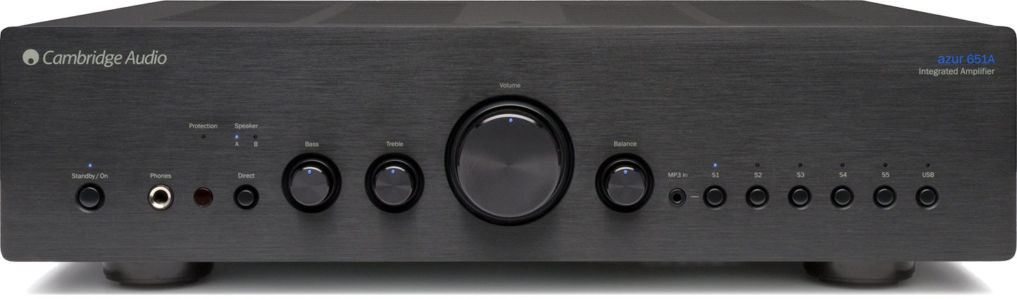
The name AZUR is assigned to the higher series of Cambridge Audio devices. Amplifier AZUR 651A is praised for its sound qualities and current efficiency. Is there anything else that can be improved in this design? Yes one can and it turns out, that quite a lot.
Like many Cambridge Audio products, this amplifier was built under the strict supervision of the accountant and the elements used for its construction are including in the budget class. This situation also has its advantages, because Cambridge Audio devices are therefore very susceptible to modifications, and the obtained results are more than satisfactory. The amplifier, with its sound and quality, matches and maintains the construction level for about 750 USD, however, the modifications I have made have shown that much more can be obtained from this construction. AZUR 651A includes several unconventional solutions, competitive products in this price class already have, for example, inputs on relays or better thought-out power supply. It can be considered that these are not very important aspects, but it is precisely these details that decide about those little flavors, that we will be able to hear or not. The construction of the device, despite some drawbacks, is not bad and my work showed, that one can significantly improve its sound at a low cost.
During my adventure with the modification of this amplifier, I learned how difficult the tuning process can be and I understood how professional tuning differs from replacing components “blindly”. In most cases, blind replacement of components, for a better class, brings a positive effect, but with some modifications you can radically change the sound and character of the amplifier, not always in advantage. That is why you should be vigilant and cautious, so that there is no situation, where we have to accept the change that involves a significant compromise.
I believe that the modifications I made have kept the character of the amplifier and at the same time improved all its aspects. I must admit that maintaining the character of the amplifier was not easy, and all the details and problems that I came across I described below.
Preamplifier modifications
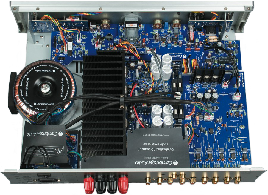
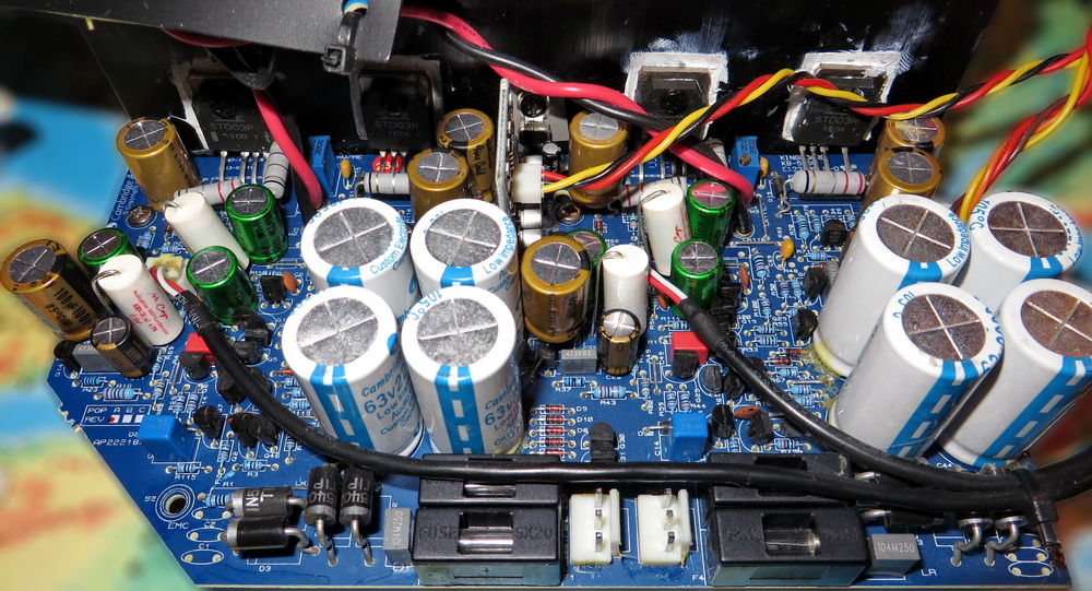
AZUR 651A is an integral construction and inside it, in addition to the module of the power amplifier itself, there is also a preamplifier module, responsible for receiving the input signal, its possible correction and volume control. The construction in terms of service has been very friendly designed. The interior has been divided into three main printed circuit board, which in addition can be easily separated from each other, so you do not have to disassemble the entire structure every time.
Removal of capacitors from the signal path in the preamplifier
Before the audio signal reaches the module of the amplifier itself, it must pass through three pairs of electrolytic bipolar capacitors, that are in its path. The first pair of capacitors is located just behind the RCA input sockets. The second pair of capacitors is located at the DIRECT / CORRECTOR switch. Interestingly, with the DIRECT setting, the signal passes through another pair of capacitors than with the attached equalizer. I have always wondered why, when switching the DIRECT / CORRECTOR, despite resetting the equalizer, I hear a change in the sound. Now I know that this was caused by the passage of a signal through another pair of capacitors and an additional pair of operational amplifiers. The “DIRECT” capacitors were shunt by foil capacitors, but the capacitors from the equalizer were not and this caused an audible change. The third and last place where the signal passes through the electrolytic capacitors is the volume section containing the volume potentiometer.
In my copy of the amplifier, the manufacturer used Fujicon capacitors. Unfortunately, Fujicon capacitors do not have the best quality of sound. They are characterized by quite dark, warm and not very open sound. In order to improve the sound quality, the manufacturer decided to shunt the electrolytic capacitors with 0.1uF foil capacitors. This solution works quite well, but it does not match the quality of capacitors such as Nichicon MUSE ES, which do not cost much at all.
The use of capacitors in so many places is caused by safety issues, so that in the event of damage to the operational amplifier, its power supply voltage is not given to other operational amplifiers. I understand this approach, but in this case I think that the manufacturer has overdone on security, and the loss of quality caused by this solution is too high a cost and I can not accept it. I decided to remove these capacitors and replace them with jumpers. At the input of the amplifier module there are capacitors, which in case of failure, will not let in unwanted voltage into the amplifier module and this is sufficient protection.
The removal of capacitors has brought a major changes in all aspects of the sound. The dynamics increased, more air appeared and the separation of virtual sources improved. The stage has become fuller and more open to the listener. The level of granularity and sibilance, which had not been too much before and not annoyed, but they were noticeable, was also reduced. The most interesting change was the appearance of a clear height dimension. I did not expect such a change, I thought that such a rarity is reserved only for more expensive constructions. Change to a huge plus, after the first auditioned song I knew that there was no return.
I am surprised that the manufacturer did not pay much attention to the issue of these capacitors. Since he already decided to use so many capacitors in the signal path, he could at least try to use better quality components. As part of the experiment, before finally I decided on the jumpers, I replaced the Fujicon capacitors with Nichicon MUSE ES. Nichicons turned out to be too analytical and too little musical in this application, but they still played much better than Fujicon capacitors.
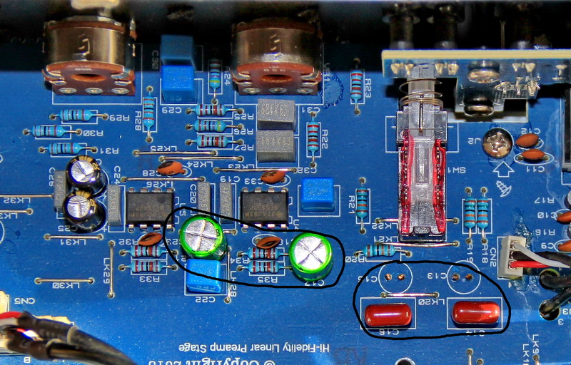
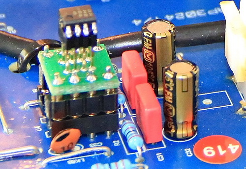
One of the pictures below showing the entrance section shows, that on the two inputs (1 and 5) I left the Nichicon MUSE ES capacitors. I decided to do this in case I had to connect an unreliable signal source to the amplifier. In addition, I thought it worthwhile to leave the channels with Nichicon MUSE ES capacitors, because of their analytical sound.
The next picture shows a pair of Nichicon MUSE ES capacitors mounted in the equalizer track and a pair of jumpers, through which the signal flows at the DIRECT setting. In the equalizer path, I also left Nichicon MUSE ES capacitors for future tests.
The last picture shows a volume section with marked places with jumpers after Fujicon capacitors.
OP AMP’s replacement in preamplifier
In the amplifier AZUR 651A applied NE5532 opamps. They are very popular constructions, providing good quality for a small price. NE5532 is worth the price, which is 1 USD. I decided that it would be worth checking if the more expensive constructions will allow to obtain a clearly better sound. At the beginning I was planning to replace only the opamp in the input section of the amplifier, but it turned out that the signal goes through three more opamps, located behind the integrated input selector and at the volume section.
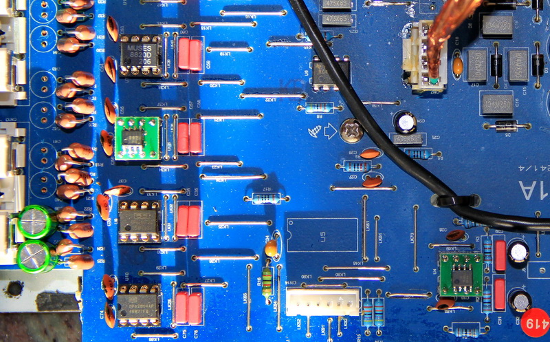
My first step was to determine what opamp should I decide on. I wanted the amplifier to keep its character of the sound, that’s why I bought a few different opamps and I spent some time to warm them up and listen. Finally, I decided that NE5532 will be replaced by MUSES8820. The exchange of the opamp on the signal input brought clearly audible changes, but only after replacing all opamps of the preamplifier, AZUR 651A got a decent kick. The dynamics and diversification of the lower registers increased. The amplifier was able to play plastically and with a diversified bottom before the exchange of opamps, but after the exchange of operational amplifiers, more contours and control at the bottom of the band appeared. MUSES8820 are much better at processing higher registers than NE5532. The midrange and top became fuller and more natural, more micro details and a lot of air appeared.
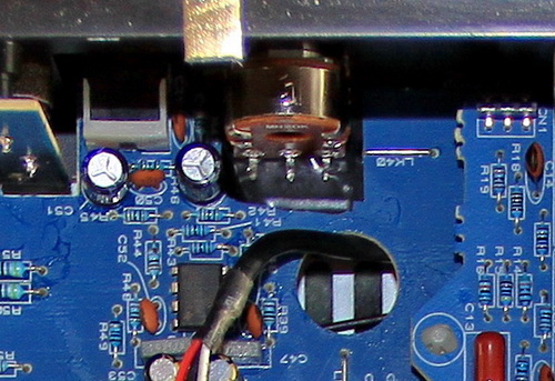
The sound of MUSES8820 and NE5532 is very similar. Both opamps are very musical and give much joy to listen. However, MUSES8820 does everything simply better, as if was cleaning the scene from fog , which almost imperceptibly, and yet limits the contact of the listener with the sound, witch reaching it. Replacing the opamp of the input section and the integrated input selector was not a problem, but replacing the other two opamps in the volume section, required some experience in the use of the soldering iron. Amplifiers in the volume section are SMD constructions in SO8 enclosures. In addition, it turned out that the previous NE5532 were glued to the circuit board, which made their desoldering difficult.
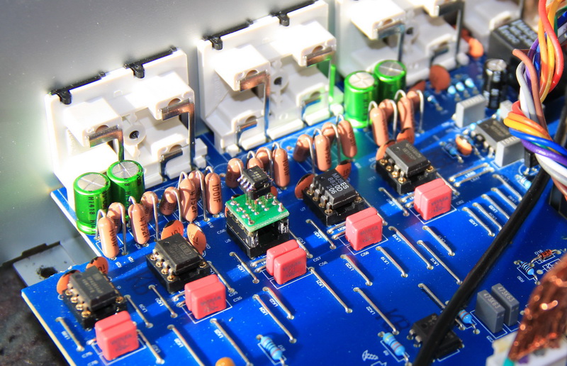
First picture below shows the operational amplifiers of the input section (on the left site) and the operational amplifier behind the integrated input selector (in the lower right corner of the image). The second picture shows a volume section with two opamps in SMD enclosures.
Before I bought this amplifier, I read many reviews. I remember that in one of them, the author very praised the solution of inputs with separate opamps and the use of the integrated input selector. Unfortunately, I do not share this enthusiasm. The use of a separate opamp for each input gives you a lot of tuning and experimenting possibilities, but it also has its dark side. All my adventure with the modification of this amplifier began with noticing, that each of the inputs is a bit different. After the tests I already know, that the differences in the parameters of the input opamps, had the biggest influence on these differences. All the factory set input opamps (NE5532) in my amplifier are Texas Instruments constructions from the same series, but the difference in the sound of each chip is really big and clearly affects the overall reception of the sound of the amplifier.
I suspect that the manufacturer decided on such an entry section solution, due to the integrated input selector, because thanks to it, does not have to worry about matching the signal. In the same way, the signal coming out of the integrated input selector goes to the next opamp and from there goes on. This solution makes the signal go through three opamps, and as you know, the signal processing by the opamp does not take place without distortion.
The price of one NE5532 opamp is about three times smaller than the price of a decent relay, so the conclusion arises itself . The use of opamps is also connected with the risk, that the power supply voltage will go to the signal path (opamps are powered by + -15V DC). This was probably one of the reasons for the use of so many separating capacitors in the signal path.
Replacing the resistors in the input section
Due to the fact that I made a small testing ground with my amplifier, I decided to check what effect the Vishay Dale resistors would have on the quality improvement, that I mounted in the entrance section. I must admit that I have noticed a slight improvement in quality, the change is subtle but clear. Vishay Dale sound a bit softer than factory metalized resistors, but for most listeners this difference can be unnoticeable. I liked their sound very much and if someone cares about refining all the details during the modification, I can recommend these resistors with a clear conscience. Replacing the resistors at all inputs is not very profitable if you do it for the sake of the principle, not knowing what will be attached to the entrance. However, if you have a source of good quality, then it is worth investing 1 USD when modifying the input, because that was the cost of exchanging resistors on one input. The values of the resistors on the input are 1k ohm and 47k ohms.
Removal of the balance potentiometer
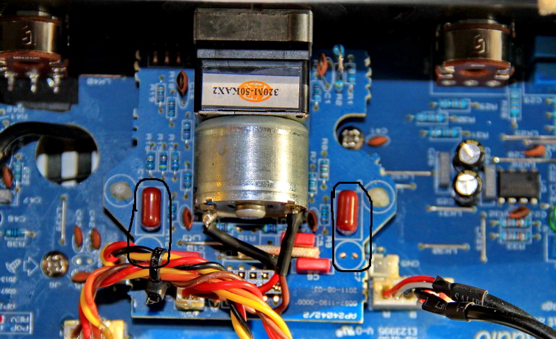
The ability to adjust the balance is a function that I have never actually used, so I decided that passing the signal through an additional potentiometer does not make much sense. The potentiometer for balance adjustment in AZUR 651A is a classic open graphite construction, which, as I found out, had a significant negative impact on the sound. I replaced the potentiometer with jumpers. Removal of the balance potentiometer from the signal path gave a clear increase in space, improvement in the higher frequencies and reduced graininess. I bent pins of the balance potentiometer, so that they rested on the board, thanks to which the potentiometer remained mounted in its place and the appearance of the front panel did not change.
Power capacitors replacement
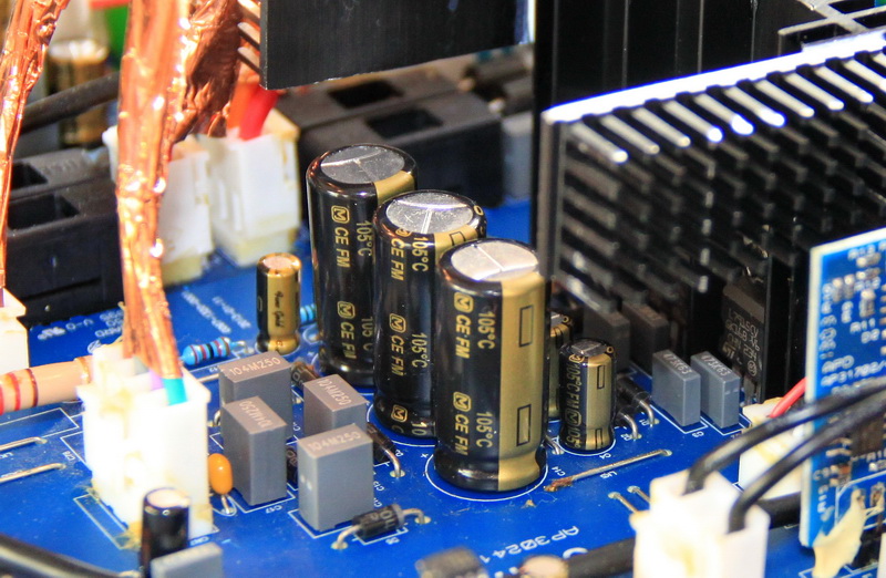
Electrolytic capacitors in the power supply have many functions, which is why their quality is of great importance. In addition to energy storage, they should be able to give away energy as soon as possible. Also they should be able to capture as much interference from the power supply and prevent them from reaching the components responsible for processing the audio signal. I decided to replace capacitors with Panasonic FM in the preamplifier section. It turned out that after replacing the capacitors, the sound became milder and the presentation of high tones improved. I also noticed an increase in dynamics. The sound clearly cleared. Thus, the Panasonic FM capacitors proved to be better than the factory set capacitors. This modification shows how important the power quality in the amplifier is. Properly thought-out organization and layout of buffers (capacitors) can have a significant impact on the final effect. It is also surprising how much interference there is in the power supply and how much of it is transferred to the audio signal.
Replacement of foil capacitors decoupling operational amplifiers
Replacing the decoupling capacitors on the power supply of opamps was an unplanned operation and I did not expect any noticeable effects after this modification. I had in my collections for a long time unused foil capacitors WIMA MKS2 with a capacity of 0.1uF. I thought that since I already have a hot soldering iron and a circuit board on the table, I will replace the factory NoName capacitors with WIMA MKS2. I must admit that the changes introduced by these capacitors were the biggest surprise for me. They were not as large as when shunt the capacitors in the signal path or exchanging opamps, but the changes were immediately noticeable.
The amplifier began to play more gently, the scene became more arranged. I once read the opinion that MUSES8820 are quite garish and I also noticed a similar tendency in my amplifier, but this garish was not annoying and I assumed that this type is so. It turned out that after the exchange of decoupling capacitors on WIMA MKS2, this tendency to garishness disappeared. The biggest changes were recorded in the upper registers and in midrange. The top gained on gentleness, the sound of the instruments became fuller and more natural. WIMA MKS2 are perfect for decoupling power supply and I can recommend them with a clear conscience. They are a great supplement when cleaning power supply from interferences.
Amplifier modification
Replacing the capacitors in the signal path of the amplifier
In my amplifier I have introduced many modifications, but the exchange of bipolar capacitors in the signal path in the amplifier module was of key importance and decided about the success of the whole undertaking. Three electrolytic bipolar capacitors were used in the signal path of the amplifier. One of the capacitors located at the very entrance of the amplifier, acts as a protection against the possibility of a DC component on the input, as capacitors in the preamplifier did and I decided to leave it for safety, so as not to let a DC component from the preamplifier, which could occur in the event of failure . The other two capacitors are necessary because, as shown the measurements, they separate the existing constant component in the amplifier module circuits.
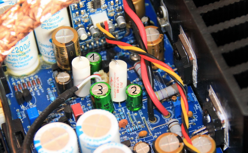
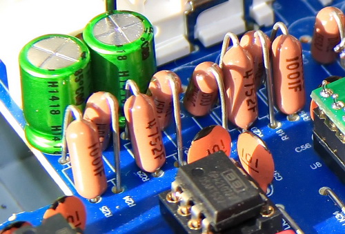
Based on the experiences from the modification of the preamplifier, I decided to replace the factory Fujicon capacitors with Nichicon MUSE ES. Unfortunately, the exchange of capacitors caused a complete change in the tonal balance. The amplifier began to play brightly. The top registers has come to the first plan, just behind it was the midrange, and the bottom of the range has been pushed somewhere far back. Listening such a transfer was very unpleasant. My 40-liter speakers with an 8″ woofer started playing like small monitors. It turned out that for such a change in the sound, responsibility bear wrong values of the capacitors. As I wrote earlier, Fujicons are dark and not very spatial, to correct their character, capacity 47uF were used. Thanks to this value lower frequencies were suppressed and a neutral tonal balance was obtained. Nichicon MUSE ES are completely different constructions, I learned about it earlier, during the tests made in the preamplifier and they have MUSE postscript not without reason. They perform very well in the entire acoustic range and their better ability to carry medium and upper registers made problem with tonal balance. I made the band alignment test by changing the capacity of capacitors from 47uF to 100uF. In the picture above, you can see capacitors before changing capacity to 100uF. This change turned out to be a bull’s-eye. The amplifier began to play neutrally and freely.
This example shows how difficult modify the device may be. In most cases, it is enough to replace the elements on elements with better quality and usually a positive effect is obtained. Sometimes, however, there is a situation where the replacement of an element on one with a better quality can spoil everything, and in this case the term “professional tuning” gains power. That is why knowledge and listening experience are so important to know what to endeavor for, because as this example shows, a better quality element not always gives a better sound.
In the picture above you can see two Mundorf Mcap capacitors with a value of 0,1uF. These are capacitors, witch shunts Nichicon MUSE ES capacitors (marked as 1 and 2). I have mentioned before that Nichicons MUSE ES are quite analytical and lack some plasticity and musicality. I managed to correct this defect thanks to the Mundorf Mcap. Mundorfs were mounted in places after foil capacitors that shunted Fujicon capacitors. This treatment was quite expensive, because 4 Mundorfs cost me almost 20 USD, but I’m happy with the change they introduced.
Replacement of the electrolytic capacitors of the amplifier
It is possible that in this place I will be accused of lack of consequence in modifications, but as I mentioned earlier, I wanted to experiment a bit and broaden my knowledge. Therefore, in the amplifier module I decided to use Nichicon FG (Fine Gold) capacitors. An interesting fact was that I had to wait quite a long time for the proper effects of the modification. Replacing the capacitors in the preamplifier was noticeable immediately after several hours. In the case of the amplifier module, I had to wait almost a week for the effects. It is possible that this difference was due to the fact that the preamplifier capacitors warmed up faster, because the all device worked 24 hours a day with a given signal at the input and disconnected speakers. The amplifier module capacitors were warming up more slowly because it required the amplifier to deliver signals to the speakers, which lasted no more than a few hours a day.
The effects of modifications were noticeable from the very beginning, but they were not as clear as I expected. The amplifier played uniformly and without life. However, after about a week, I started to notice changes to the plus. The dynamics of the lower registers rose and it became more diverse, and more air appeared in the lower registers. It’s hard for me to describe what happened to the midrange and the top due to this modification, due to the longer time in which the changes took place, but the improvement of the lower range was clear, for a big plus and even only for lower registers was worth replacing the amplifier module capacitors. In the changes introduced by Nichicon FG and Panasonic FM, I noticed a clear difference, although I do not know if it does not result from diferent applications of these capacitors. Nichicons FG are very dynamic and analytical and Panasonic FM capacitors are gentler and slightly warmer.
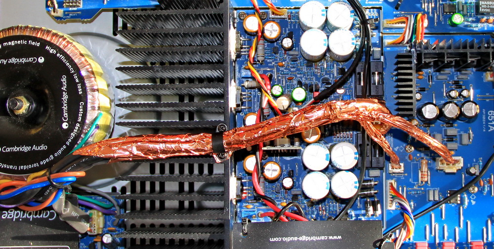
Shielding of power wires
This is a modification, on which idea I fell completely by accident. Before I finally chose the capacitors responsible for the shunting Nichicon MUSE ES in the signal path in the amplifier module, I carried out several tests. Ultimately, I decided to use the Mundorf Mcap capacitors, but their use is not a cheap solution, so I tried to find a cheaper alternative (Vishay MKP1837, Wima MKS2, Jantzen cross-cap). From the amplifier module board, in the place for the shunt capacitors, I led the wires to which I assembled the tested capacitors. It turned out that the addition of shunt capacitors has a negative effect on the quality. The top became sharp, sibilants appeared, the scene became chaotic, and the lower registeres was withdrawn and hard. I emphasize that I have not noticed any typical deformations/noises in the form of humming, hissing or other sounds that I should not hear. Simply, the recordings have lost their quality.
For occurrence of such interference was responsible placing the shunt capacitors too close to the power wires. As you can see in the picture below, the power wires are quite unfortunate placed above the amplifier module board and transmit the disturbances to the signal path through the shunt capacitors hanging on the test wires. The problem with additional interference disappeared when I soldered the shunt capacitors to the amplifier circuit board. Following this lead, I decided to check if the additional shielding of the power wires would have a positive effect on the sound of the amplifier. I wrapped the power wires with copper tape and connected this tape to the housing through a screw on the heat sink. The effect was amazing. They were not any radical changes, but I noticed that there was more space and air. What is certain is that, if I noticed some changes, it mean, that power wires were still transmited interference to the signal path. Probably the manufacturer decided, that the interferences is at an acceptable level and gave up shielding the power wires. I think that shielding is necessary because the more I listened to the music, the more differences introduced by the added shield, I began to notice.
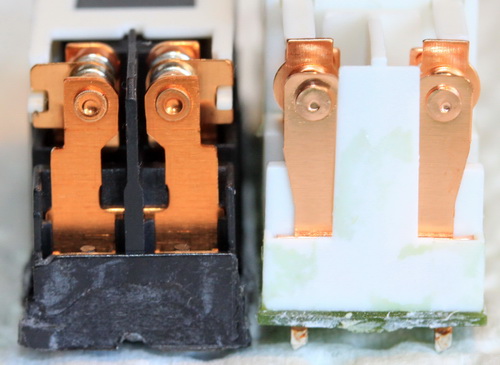
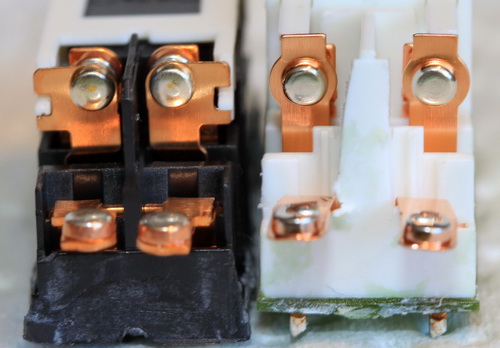
Output relays replacement
Before the signal reaches the output terminals of the amplifier, it passes through the output relay. It is a classic solution allowing to manage the output and its division into output A and B. Previous modifications have changed the amplifier significantly, removing many of its disadvantages, however, these improvements have caused that the disadvantages previously well masked, now began to come out to the first plan. It turned out that the output relays used by the manufacturer are of poor quality and constitute an audible obstacle to the signal. The symptom of a malfunction of one of the relays was a quieter sound of the right channel. The problem did not always occur, sometimes the channel played well, sometimes slightly weaker, sometimes much less clearly. The problem intensified when I switched to bi-wiring. I connected tweeters to output A, woofers to B. One day, when the right channel was playing more quietly, I decided to switch between outputs A, B, A + B and noticed that a significant difference in volume occurs on tweeters, woofers play equally, and so the suspicion fell on relay from output A. I decided to buy RELPOL relays (RM84-2012-35-1012), I was wondering about the version with gold-plated contacts, but due to lack of availability, I bought a cheaper version for 2 USD. What I heard after the relays exchange really surprised me. Of course, the difference in the volume of the channels was eliminated, but the change in the sound surprised me the most. The biggest difference is heard on the top of the band. The higher registers became milder and more natural. I’m happy with this modification.
I was surprised by the introduced changes so much, that I decided to disassemble and compare the relays. The following pictures show the difference between the relay used by the manufacturer (MASSUSE ME-11 012-2z4) and RELPOL. I know that visual judgment often has nothing to do with sound qualities, but in this case it perfectly reflects the difference in the sound of one and the other relay. Black is the MASSUSE relay, white is the new RELPOL. Both relays were hermetically sealed, however, the one used by the manufacturer looks as if air was coming in and the contacts were oxidized. The only logical explanation is the long “aging” of the contacts before they were mounted into the inside of the relay.
Summary
The modification was a complete success. The amplifier has gained in all aspects and without any compromises. Each change has added a larger or smaller brick to the whole, and the final effect is very rewarding. The modification did not change the amplifier into the reference unit, it still has some disabilities. However, disabilities that can be listened, belong more to the class of tastes than defects. The amplifier has risen to a completely different level and I bet it would be able to rub the nose of not with one of the more expensive constructions. Azur 651A now plays like a completely different amplifier, and when I reach for what it was before modification, I’m amazed at how much I managed to achieve.
The biggest change that I really enjoy is the improvement of the stage. There is now a lot of air, and determining the position of a virtual source in three dimensions does not require any effort from the listener. The high tones have become mild and full. I did not notice any tendencies to sharpeness or graininess. I notice subtle sibilants only in tracks, that have a tendency to them or result from the disadvantages of the recording itself. A lot has also changed in the lower registers. Here also more air and dynamics appeared. The bass diversification also increased. Azur 651A had no problems with processing lower registers before the modification, but now this ability has improved significantly. Bass can be really powerful and comes with incredible freedom.
A lot has changed in the reception of my wires. Qed Ruby Anniversary Evolution, previously considered by me to be a mistake, due to its graininess and sharp top, now works great, plays gently and creates a wide stage. I can confirm the opinion that this wire needs to fit into the system, and writing in a different way, if the system has any defects, the Qed Ruby Anniversary Evolution will certainly show them all. Van Den Hul Clearwater, who was my favorite before modifying, is now incredibly gentle and analog, but his tendency to narrow the scene has increased. Van Den Hul Clearwater can play widely, but unlike the Qed Ruby Anniversary Evolution, it requires a physical speakers spacing. Currently, the Qed Ruby Anniversary Evolution is powering my tweeter and the Van Den Hul Clearwater powering woofer. Yes, the wire that devastated the upper registers before modifying the amplifier now powers the tweeter. This is probably the best way to show how big changes took place in the AZUR 651A amplifier.